
The Induction Coil
"Now does my project gather to a head
My
charms crack not, my spirits obey, and time
Goes
upright with his carriage. How's the day?"
Prospero, "The Tempest"
At last! It lives! My novel sidetone generator is complete! (Cue thunder & lightning, maniacal laughter, clanking chains, baying hounds etc.)
I've wanted one of these things since I was a lad, it has only taken thirty years but I've finally gone and done it. The details of what to do and how to do it were obtained mainly out of reprints of relevant constructional articles from Lindsay Books (sadly no longer extant) One or two tweaks I had to discover for myself.
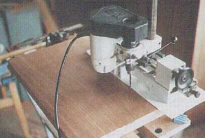
The induction coil primary was wound with a couple of layers of 1,7mm wire. This can be seen protruding from the centre of the coil to the left in the photo below. Around 200 turns were used in total. The coil covering is heavy photo card from a stationers, later on I sprayed it with aerosol wax polish and it attained a deep shine, just like the ebonite sheet which was once used for this job. The primary core is packed with about 11 ounces of 1mm iron fence wire, which was annealed in a barbecue charcoal fire.
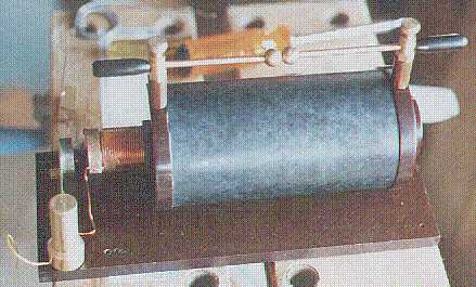
The primary former is a length of cardboard tube, and both end cheeks on the primary former are also short lengths of cardboard tube which were a good slip fit, stuck on with PVA wood glue. This slides inside a length of Tufnol tube, 1,5 inches outside diameter and approximately an eighth of an inch wall thickness obtained from RS Components (http://rswww.com) which also provided Tufnol sheet for the base and main coil end cheeks, and more half inch Tufnol tube for the EHT standoffs also seen in this picture. The phosphor bronze balls used as discharge electrodes are half inch diameter, sadly no longer available, but brass will do as well and small doorknobs (really intended for chests of drawers) can be obtained from several chains of DIY warehouses, in fact I used a one inch doorknob as the discharge ball on the Tesla coil. All other metal supplies and many hand tools (e.g. taps and dies) used for projects on these pages, I obtained from Macc Model Engineers, 45a Saville Street, Macclesfield, Cheshire, SK11 7LF, tel. 01625 433938 - their service is first rate, and they are now on the internet!
The silver contacts I used for the interruptor, around a quarter of an inch diameter, were from a piece of silver I've hoarded for years. This I melted, cast into an ingot, er - lump, and then machined to size. Silver has the curious property that, when molten it absorbs oxygen from the air, which is expelled again when the metal solidifies. The silver castings are riddled with minute blow-holes from this cause, irritating but harmless.
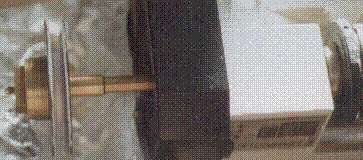
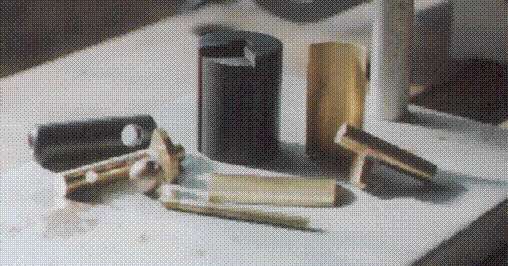
The picture above shows the ever-versatile Unimat 3 being used to wind the "pies" of the secondary, and a variac was used to regulate the speed. The winding gear is a simple thing made from a couple of thin Tufnol sheets with a brass spacer, and it runs on a rod which passes through the Unimat headstock as the pies are too big to swing over the lathe bed. The wire was guided by hand, moistening my fingers with linseed oil. The secondary is constructed from around 2lbs of 42swg enamelled and double silk covered wire. I was lucky to find this as a production over-run at the Scientific Wire Co. (http://www.wires.co.uk) otherwise it would either have been unobtainable or have cost a fortune. It's worth making a telephone or email enquiry as not all they have is on the website. The coil gives (unloaded) a spark of an inch and a bit between half inch phosphor bronze balls. It is very hot and will ignite paper and card rapidly. The completed pies are shown below. A ruler gives an idea of scale.
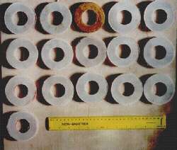
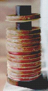
Two of these were lost in the initial test when the insulation (here paper disks) blew through. The insulation was replaced with three layers of card soaked in melted beeswax per pie, and molten wax mixture was painted on around the seal between the Tufnol tube and the card washers. The pies were insulated with a molten mixture of beeswax and rosin (from a musical instrument shop) just as the originals. This was brushed on with a fine paintbrush whilst winding the coils; the motor was slowed to a crawl whilst doing this. The unevenly-insulated pies were then cooked gently in an oven at around 50C just to soften the wax mixture until the insulation became homogenous. The pies, part-assembled on the Tufnol tube (with the initial paper insulation) are shown below.
To mount the coil I chose a piece of West African mahogany from South London Hardwoods (http://www.slhardwoods.co.uk) and I also bought a couple of sticks of ebony. The latter were used to make handles for the coil discharge electrodes, for the core of the Ruhmkorff commutator switch, and for the pillar on which the Tesla secondary stands. Hard rubber, called ebonite, was used for this, but dry wood seems OK at these voltage and power levels. To my knowledge, there is just one compounder of ebonite left in the UK, in Manchester, and it's fine if you want a few tons!
The design of the radio frequency part of this project called for months of experimentation with the part-made induction coil, at that time screwed to a piece of very tatty plywood whilst many design changes were made. It was decided to use a primary of two layers of eighth inch brass boiler band from Macc, supported on wooden dowels which were soaked in melted beeswax. It is essential that the holes for these are drilled exactly vertically in the baseboard, otherwise the primary will look very uneven and will not contact all of the octagonally-spaced supports. Here the Unimat is being used to sink these holes.
More woodwork was needed when it came to hiding the Fizeau condenser across the contact breaker points. The condenser used was an old WW2 vintage Dubilier nitrogol 2uF 400V unit. It had already been established that 1uF was not enough, and the voltage rating is essential to cope with the back emf. Here's the inletting nearing completion. I placed a ruler across the bottom of this shot to give an idea of scale, but the divisions aren't very visible, unfortunately.
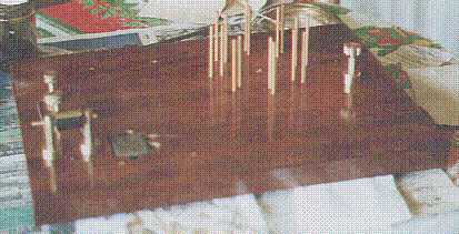
The wood looks quite pale prior to French polishing with Liberon button lac dissolved in methylated spirits. It was rubbed down with sandpaper between coats until all the wood pores were filled, and thereafter rubbing down with Liberon 0000 steel wool and linseed oil. It's the first time I've ever tried doing it and it's neither easy nor perfect to look at - but not a bad job for a novice. The near-finished baseboard, together with a few components, is shown below. The octagonally-spaced dowels for the boiler band primary can clearly be seen, and the condenser is well fitted in its hole. Aerosol wax polish should not be used on shellac finishes, as the solvents in it will dissolve the French polish which took you so long (and so many attempts!) to get looking good. Use the solid stuff in tins instead.
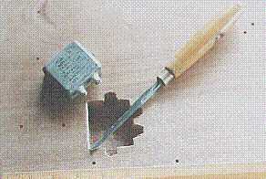
Bottom left in the above photo is part of the Ruhmkorff commutator switch. This was a most infuriating thing to make, requiring some of the most dubious soldering I have ever done (with a 50-year old 230W thermostatic iron!) but we got there eventually . . . final polishing was with some amazing Japanese Tamiya abrasive paper, down to 2000 grit, which I got from Brouckx model shop in the Koning Albertstraat, Hasselt, Belgium. The components of the switch appear here.
The Tesla secondary was around 700-800 turns of spare wire left over from the induction coil, around an inch and a quarter diameter and seven and three quarters long. It's very unevenly wound, the turns even cross over at a few places! The coupling coil is an unknown number of turns (try until it works!) of 36swg tinned double silk covered copper, also from Scientific Wire, wound on a cardboard pot which once held Fair Trade cocoa powder. The condenser is a cheat. I was going to use an ex-Admiralty WW2 vintage 28kV 0,0011uF mica condenser, but its losses hampered spark production (the input to the induction coil is only 30-70 watts or so - my QRP radio friends will cringe - but that's not much to make sparks with, especially given the inefficiency of induction coils) so I used ten 0,01uF 1kV polypropylene units from RS Components in series, hidden inside the wooden box. The odd value of the ex-Admiralty mica is due to its being exactly one standard Admiralty "jar" of capacitance in old units! The output from the Tesla coil is shown below.
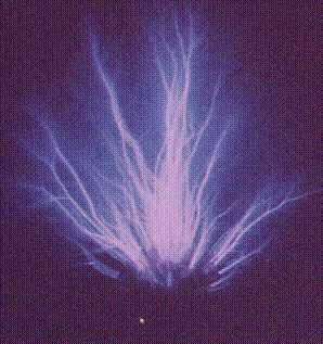
The sparks are maybe 1,5-2 inches long. I have changed the colour balance of the photo, as the original is too blue. This is still not right, but it's closer to the purple which your eye actually sees. There's an evident difference in the spectral sensitivity between eye and film, especially at low light levels. In operation, the most important thing is to ensure that both the interruptor contacts and the sparking balls are kept clean. Every ten minutes or so of operation necessitates a break for cleaning with abrasive paper. The setting of the spark gap is also very critical to success, and the sparks from the Tesla coil make a strange squeaking noise when all is tuned correctly. A good ground connection is important, and a large metal object (I have used a big metal case maybe five feet by two by two) is better than the ground rod I use for my amateur radio transmitter.
The only problem with this thing is the copious quantities of ozone emitted (honestly, you can't have it switched on for more than a minute without needing to leave the room, it's that bad!) With the fundamental around 2Mc/s, plus the emissions of the interruptor, it does cover all amateur bands though . . . simultaneously!