The
Spark Transmitter. 4. Inductive Coupling of Tuned Circuits.
"All is riddle, and
the key to a riddle is another riddle."
R.W. Emerson
Will
we ever get to the load? Well, it's getting closer . . . trust me,
I'm a doctor.
Inductive Coupling.
Having generated power at rf, it is
necessary to transfer it from the primary circuit where it originated
to the secondary circuit where it will do something useful.
Remembering the requirements of the maximum power theorem, it is
clear that the conditions required are those of an impedance match.
 In
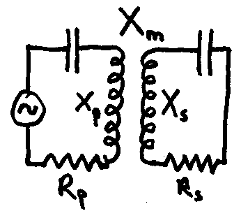
the diagram, the primary and secondary coils are coupled inductively
by means of a mutual inductance M. This has a reactance at the
operating frequency Xm. For perfect matching, the
resistance coupled into the primary circuit must be equal to the
resistive load which the generator expects to see. If the load is
itself reactive, then to get a perfect match two out of the three
reactances Xp, Xs, and Xm must be
variable. Fortunately, if primary and secondary are tuned circuits at
resonance, things become greatly simplified and we have the
possibility of obtaining a perfect match purely by varying the mutual
inductance coupling. This we do according to the equation:

where Rp and Rs
are the resistances associated with both circuits. (The value of the
mutual inductance M can then be calculated if we know the frequency
of operation.) Well, what exactly are these resistances? For the
primary circuit, Rp is the resistance associated with the
generator (remember the maximum power theorem!)
But what is Rs? That is a
harder question to answer. It also seems likely, for a Tesla coil
secondary, that it will vary according to whether a spark is being
produced from the top electrode or not. At least with an aerial it
will be constant. With a resonant aerial in fact it's fairly easy,
being equal to the sum of the resistive losses in the aerial, the
ground and the radiation resistance. The radiation resistance is a
fictitious resistance, which if it was included in the aerial would
cause as much power loss through heating as the loss of power due to
radiation from the aerial. So in the case of a Tesla secondary, what
we need here is a "spark resistance" which would cause the
same amount of power loss as is caused by spark discharge from the
top electrode. It is by no means easy to see what value this should
be. We can, however, state with certainty that it is unlikely to be very useful trying to reduce the rf resistance of the secondary to a value much below that of the ground connection, as the two act in series.
Fortunately, we can be ignorant of
the exact requirements here and adjust the mutual inductance coupling
by the physical separation of the primary and secondary coils and,
according to time honoured wireless practice, "tune for maximum
smoke"! [You can usually tell when you've damaged an electronic
component because the smoke they put in it at the factory leaks out.
I don't know who it was who invented smoke as a means for indicating
faulty components but all I can say is, it's a jolly clever idea and
I wish I had the patents on it.]
One of the reasons (by no means the only one,
nor, as it happens, anything like the best one) why Tesla secondaries
give bigger sparks with larger top capacitances is because there is
often insufficient mutual inductance coupling for perfect impedance
matching (this may be because decreasing the separation between the
coils causes sparking into the primary) and when the top capacitance
of the secondary increases, the resonant frequency drops, more turns
are needed on the primary (which may be too small in relation to the
primary capacitance) and the effective size of the primary is
increased, thereby increasing the proportion of input power converted
to rf, and increasing the mutual inductance and improving the match.
It may also happen that reducing the secondary reactance
(corresponding to the drop in frequency) improves the impedance match
and we get a better power transfer from that cause too. (We'll come
to the best reason for big secondary capacitances later.) But there's
more.
The mutual inductance coupling
between primary and secondary can be related to their self-inductance
by means of the coupling constant k:

Notice that since k is defining the
relationship between magnetic flux linkages in the circuit, it can
never be greater than 1. A value of 1 means that all the flux
produced by the primary is linked with the secondary and vice versa.
A value of k greater than 1 would mean that more than all of the flux
produced by the primary is linked with the secondary and thus values
of k greater than 1 (and I have seen people claim it!) means you have
a problem! In fact, k = 1 is never achievable! The closest you are
likely to get is in the output transformers of high quality valve
amplifiers where primary and secondary are split into interleaved
windings, and in specialist types of instrument transformers where
the construction is similar. Power transformers used for supply
distribution are also quite good, fortunately for the supply
companies and the end user. Neon sign transformers and welding
transformers are examples of designs where the value of k varies
considerably with the load and is sometimes a lot less than 1.
Transformers of this latter type are
called "magnetic leakage transformers" because the design
is such that a large proportion of the flux generated by each coil
can escape from the magnetic circuit associated with the other coil.
Under load, the proportion which "leaks" increases. This
gives intentionally poor power regulation and ensures that when a
short circuit is placed across the secondary (the striking of the
welder's arc, the conductive breakdown of the neon gas, or the
flashing over of the primary spark gap) the output voltage is
suddenly reduced until the "fault condition" is removed.
Mr. Melville Clapp-Eastham in the USA can be credited with the
introduction of this type of transformer for spark transmitters, and
his Model E transformer has a prominent place in wireless history.
Similar results can be obtained from a power transformer of the
closely coupled type if there is an external inductance (choke) in
series with the primary and this external choke provides the
necessary "leakage inductance".
The coupling constant is independent
of the number of turns in a coil. The number of turns in a coil
determines the magnetic field which will be produced for a given
current. The coupling constant is concerned with how the lines of
magnetic force produced by one coil interact with another coil, and
hence the coupling constant between two air spaced coils depends only
on their physical size and disposition in space. Hence to obtain the
best coupling between primary and secondary in an air-cored
transformer we can only change the size and spatial relationships of
the coils. With a tapped coil it may be noticed that changing the tap
position changes not only the self-inductance but also the coupling
constant. This is of course because when the tap is moved to a
different position, the effective size and spatial relationship of
that coil are changed as well as its self-inductance.
When we have the critical coupling,
which exists when the voltage output is optimised, then we have an
additional relationship between kc the critical coupling
constant and the Q values of primary and secondary:

The value of coupling constant is
important in a spark transmitter because the tightness of coupling
determines the rate at which the primary loses power to the
secondary, and hence determines decrement, damping, sharpness of
tuning (loaded Q) and intensity of current at resonance (and hence
secondary voltage in a Tesla coil.) Remember those nice graphs
showing the logarithmic decrement and loaded Q? The graph of
decrement d = 0.09 and loaded Q =
34.6 corresponds to the critical coupling constant having a value of
kc = 0.17, which, from the records left by the old-time
spark wireless operators, is around the maximum which can be used
with a quenched spark gap of multi-plate construction. Hence for a
critical coupling constant of kc = 0.17, the product QpQs
must be 34.6. We can of course split that product between a wide
range of possible Qp and Qs values! If both are
equal to Q = 5.88 (the square root of 34.6) the decrement of each
circuit individually is given by the graph of d
= 0.53.
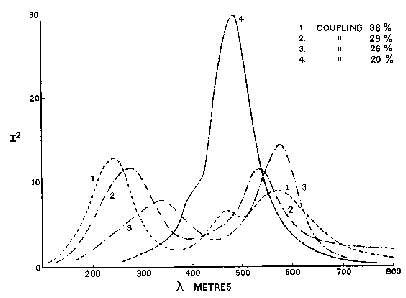
The diagram shows the effect of
varying the coupling on the frequency distribution (read 'logarithmic
decrement') of a spark transmitter. As the coupling is increased much
beyond 20%, k = 0.2, the frequency spread increases dramatically,
indicating that the logarithmic decrement has increased and that
loaded Q has decreased. The square of the current, plotted on the y
axis, also plummets drastically.

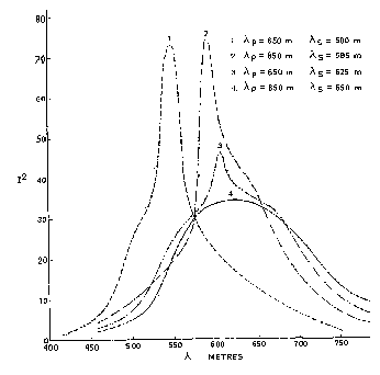
The next diagram shows that, in order
to get the highest possible secondary current, the primary and
secondary circuits have to be slightly detuned. In each case the
primary circuit remains tuned to a wavelength of 650m, whilst the
aerial circuit (secondary) is varied from 500 - 650m. The best result
is for 585m. This was obtained in an experimental test circuit chosen
to demonstrate the effect clearly, and the best detuning is here
about 11%. For the average aerial and coupling k=0.17, the detuning
was normally about 3%.

Curves like these are recorded by
coupling an rf ammeter into the circuit. I have seen circuit diagrams
in which the meter is placed directly in the primary circuit, but
evidently these were low voltage circuits (possible with the quenched
gap which will operate on just a few hundred volts) and it is more
usual to couple the meter to the aerial circuit and then indirectly
by means of a coupling loop. A thermocouple ammeter would be the
instrument of choice, but these curves were recorded most likely with
a hot wire meter, whose deflection is proportional to the square of
the current - hence the plot of I2 on the y axis.
The mutual inductance coupling
ensures that everything critical to the operation of the spark
transmitter (or Tesla coil) is dependent on just about everything
else, and that is why trying to find the global optimisation for a
Tesla coil to give the biggest spark for a given input power is so
very difficult. It isn't that we have such an enormous number of
variables - it's the interdependence of all of them simultaneously on
each other!
All of which goes to show how very
complicated the inductively coupled spark transmitter (or Tesla coil)
really is. It's a nice demonstration of the fact that there is not
necessarily a direct correlation between the number of components in
a circuit and its complexity of operation. The spark transmitter
circuit is one of the simplest - just seven components (power
transformer, primary capacitor, primary inductance, primary spark
gap, secondary inductance, secondary capacitance and mutual
inductance) and yet a detailed description of its operation would
require a lot more space than this and cartloads of higher
mathematics. Any electrical circuit can be broken down into just four
fundamental 'units' - inductance, capacitance, resistance and mutual
inductance - and with just seven components, this circuit has the
lot.
As a mere radio ham tinkering outside
my sphere of professional competence I can only scratch the surface.
I am left gasping with admiration at the achievements of the old
timers who built and operated spark transmitters and Tesla coils
often without a clue as to the frequency of operation or technical
knowledge much above Ohm's law. They did it, of course, by a
combination of knowing inside out what there was to know, by
meticulous method and by sheer patience and dogged determination.
Oh, by the way. We have now arrived
at the load.
We're not through yet though. The
next section looks at transmission lines and magnifier circuits.
Back
Homepage
 In
the diagram, the primary and secondary coils are coupled inductively
by means of a mutual inductance M. This has a reactance at the
operating frequency Xm. For perfect matching, the
resistance coupled into the primary circuit must be equal to the
resistive load which the generator expects to see. If the load is
itself reactive, then to get a perfect match two out of the three
reactances Xp, Xs, and Xm must be
variable. Fortunately, if primary and secondary are tuned circuits at
resonance, things become greatly simplified and we have the
possibility of obtaining a perfect match purely by varying the mutual
inductance coupling. This we do according to the equation:
