Transmission Lines and Magnifiers
"Rigour is a much misused term, and not only in expository writing but in original scientific investigations it is too frequently another name for lack of a sense of proportion."
Sir Arthur Eddington
Having arrived at the load, we can cast a rearwards glance as it were and see if it were possible to get here some other, better, way. One of the things which struck me when I began using Tesla coils as dummy loads for my spark transmitters was that the process of simply sticking the secondary into the primary was a bit hit-and-miss when it came to both the coupling and the impedance matching. Nothing I have ever seen in valve transmitter circuitry gets anywhere near this level of crudity. I never fail to be impressed by how well such an incredibly simplistic and inflexible approach actually works in practice.
Then I considered the Tesla magnifier. A curious-looking beast, I thought. I wonder why it is put together like that? The answer was not long in coming. The characteristic base-feed impedance of a Tesla secondary is of the order of a thousand ohms, at least when a spark is being drawn. It might, under various conditions, be five thousand or ten thousand. The point is, it is of the order of a thousand. Now, this is highly inconvenient, as we shall see, but it did present Tesla with an alternative method of coupling and matching to the hit-and-miss "stick-the-secondary-in-the-primary-and-see" method, which at that time was quite probably the best that anyone could do.
Here we have the original magnifier, with a minor amendment or so in the primary circuit. N1 simply allows the regulation of resonant charging and helps the quenching, particularly if a power transformer, as opposed to a magnetic leakage transformer, is being used. The important parts are the coil marked Lx and the wire marked TL. The power from the spark transmitter must be conveyed by means of a mechanism which is a good impedance match between primary and secondary (maximum power theorem!). The coil Lx plus transmission line TL (for that is what it is) approximate to this. A single wire a metre or two above ground has a characteristic impedance of the order of a couple of hundred ohms, give or take. The coil Lx with its self-capacitance, and the loading of the Tesla secondary, constitutes an impedance of thousands of ohms or so, give or take. We thus have a reasonable match between the base feed impedance of the Tesla secondary (when sparking, that is; it is much, much lower when not sparking) and the coupling and matching system. We also have, alas, several problems.
This is a high impedance matching system. This means that, for any given power level, the voltages will be higher than if it was a low impedance matching system. For example, under pure sinusoidal conditions, and with a power of 1kW, in a 1kW system we would have 1000V. Under damped wave conditions, the initial peak intensity will be several times this, say 5kV. In a 50 ohm system, that same kilowatt will produce just 220V, maybe 1kV under damped wave conditions. The voltage is equal to the square root of {the impedance times the power}.
The second problem is that there is a factor of maybe five or so between the characteristic impedance of the transmission line and the base feed impedance of the Tesla coil, and between the transmission line and LX. This gives rise to standing waves on the transmission line and these give rise to an increased voltage on the line and top of the magnifier coupling coil. If our pure, sinusoidal kilowatt was flowing through a 1kW system it would produce just 1kV, but a mismatch into 5kW will lift this to approximately 2kV thanks to the standing waves. Under damped wave conditions this is more likely to be 10kV peak. So the voltage problem gets worse with the mismatch on the line. Unfortunately, the design provides no simple way to make any adjustment, the only possible adjustment being to add or remove turns from the coupling coil, which is hardly convenient in use.
The next difficulty is that it is very hard to couple power effectively into a high impedance system from a low impedance primary when the system is air cored, which is what we have. It gets harder still when there is an impedance mismatch on the transmission line. To do it needs a high value of the coupling constant k; we need tight coupling to get efficient transformer step-up action and hence we need to reduce leakage inductance. This gives rise to the third of the problems associated with magnifier systems, that the primary and coupling coil Lx need to be physically very close to each other. This aggravates the difficulties associated with the high voltages inherent in any high impedance matching system, especially where there is additional voltage rise due to mismatch and standing waves, namely the often-encountered problems with insulation and one coil sending sparks into the other.
The fourth problem derives from the third. Owing to the fact that a high value of k is needed in a low-to-high impedance coupling and matching system, there are severe problems with quenching at the gap. Hence the addition of the choke coil N2 of a few tens of millihenries. Spark wireless operators, who must on occasion have had an awkward, high impedance aerial to deal with, suffered exactly the same problem and evolved this solution. Normally, there are sufficient gaps such that the spark refuses to jump all the gaps in the multi-plate arrangement shown. Even on maximum voltage from the transformer in the power supply, those last two gaps will not conduct. However, if they are bridged by a choke coil, the potential of the end gap is communicated to the end-but-two gap. Now the main spark can jump, but when it hits the end-but-two gap the current cannot pass through the choke coil. However, there is now no problem in jumping two gaps. So the choke coil provides a means of stretching the spark over an extra number of gaps and hence when there are quenching problems, this little dodge saves the day. I have tried this and it certainly works, but under conditions where there are no quenching problems, the extra gaps actually make things worse instead of better, due to the extra resistance in the primary circuit. I have no doubts that if my primary circuit was experiencing quenching difficulties, this old 'wrinkle' would do the job.
So we now have a question: is there a better way? Answer: yes.
Enter the low impedance magnifier. This, as will be screamingly obvious to old thermionic valve radio fans, is nothing more than good ol' 50 ohm tuned link coupling, 1930s vintage.
I have shown the primary circuit in the "balanced" configuration as it might be if you used a centre-tapped secondary on the power transformer. It isn't essential to use such a primary circuit with e.g. neon sign transformers, but it offers the possibility of earthing the mid-point of the coil Lp, though this is by no means obligatory. Placing the link coil at the centre of a balanced primary reduces stray capacitive coupling to the link LL because there is then little in the way of voltage difference between them. Using a "single-ended" primary, a similar reduction in stray capacitive coupling may simply be achieved by placing the coupling coil LL at the earthy end of the primary. If things get problematic regarding stray coupling, you simply interpose a Faraday screen between the two coils. I do not, however, expect any serious problems caused by stray coupling in this application as the operating frequencies are quite low, typically low hundreds of kc/s.
The coil LL is brought to resonance by the capacitor CL and the other end of the low impedance transmission line is attached to the secondary at two places, the base and by means of a tapping point. The reactances of the primary Lp and Cp, LL and CL need to be calculated on the basis shown before in a previous installment. The primary circuit needs a reactance of around 400 ohms for each component as does the link circuit, and this will give a loaded Q value of 8 for both circuits, which from decades of valve transmitter development has been shown to be very forgiving and non-critical. The base tapping points on the Tesla secondary are obtained in the time-honoured manner of radio amateurs: guesswork.
Actually, the tapping points aren't quite as crudely anticipated as that. In a parallel tuned circuit with impedance Z, the impedance ratio of a tapping point between that point (say Z0) and Z is equal to the square of the ratio of the turns of the two coils.
 Let's
say we have a coil of 1500 turns which, together with top hat
capacitance at the self-resonant frequency has an impedance of 50kW.
If we wish to tap it at the 50-ohm point, then the impedance ratio is
1000 and therefore the turns ratio is 31,6 i.e. we tap at the 47th
turn. This calculation is seldom exactly matched by reality, and it
is usual to supply a number of tapping points either side of the
calculated position to allow for adjustment. Not knowing if this idea
was going to work at all with a Tesla secondary, I made just one tap
at the calculated position for my "technology demonstrator".
It was good enough to show that the idea worked, and also good enough
to show that more adjustment is necessary - the same coil in the
usual plain inductively coupled non-magnifier configuration gives
around 30-35cm sparks whereas in low-Z magnifier configuration it
would not break out and to a grounded wire gave only 13cm sparks.
There was plenty of clearance between the primary and link coils;
indeed the best results were obtained with the two barely
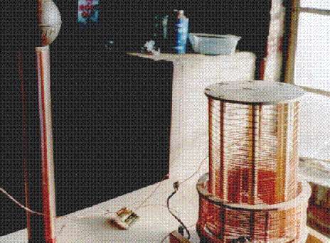
overlapping, indicative of the benefits of a loaded Q of around 8. In subsequent experiments I have been able to show that the tuning on this configuration is extremely sharp (having reduced some 2250V mica capacitors used to tune the link coil to a smoking mess!) which may even indicate an excessively high loaded Q greater than 8, although my feeling is this was simply due to mistuning, as mobile whip aerials for "Top Band" 1,8-2Mc/s are renowned for their very narrow bandwidth and critical tuning, and Tesla coils are of course far worse viewed from this perspective. My experiments with this low impedance matching system are continuing. This experimental configuration is shown below. The Tesla coil proper is to the left, the primary and link coils to the right, both the latter using skeleton former construction. The primary is the short, wide coil and the link coil sits inside it, being rather taller. The top ten turns of the link coil are widely spaced to allow connection of a crocodile clip without shorting to adjacent turns. The tapping point on the Tesla coil can be seen at the very base of the Tesla coil to the right, just above where the wire changes colour.
Let's
say we have a coil of 1500 turns which, together with top hat
capacitance at the self-resonant frequency has an impedance of 50kW.
If we wish to tap it at the 50-ohm point, then the impedance ratio is
1000 and therefore the turns ratio is 31,6 i.e. we tap at the 47th
turn. This calculation is seldom exactly matched by reality, and it
is usual to supply a number of tapping points either side of the
calculated position to allow for adjustment. Not knowing if this idea
was going to work at all with a Tesla secondary, I made just one tap
at the calculated position for my "technology demonstrator".
It was good enough to show that the idea worked, and also good enough
to show that more adjustment is necessary - the same coil in the
usual plain inductively coupled non-magnifier configuration gives
around 30-35cm sparks whereas in low-Z magnifier configuration it
would not break out and to a grounded wire gave only 13cm sparks.
There was plenty of clearance between the primary and link coils;
indeed the best results were obtained with the two barely
overlapping, indicative of the benefits of a loaded Q of around 8. In subsequent experiments I have been able to show that the tuning on this configuration is extremely sharp (having reduced some 2250V mica capacitors used to tune the link coil to a smoking mess!) which may even indicate an excessively high loaded Q greater than 8, although my feeling is this was simply due to mistuning, as mobile whip aerials for "Top Band" 1,8-2Mc/s are renowned for their very narrow bandwidth and critical tuning, and Tesla coils are of course far worse viewed from this perspective. My experiments with this low impedance matching system are continuing. This experimental configuration is shown below. The Tesla coil proper is to the left, the primary and link coils to the right, both the latter using skeleton former construction. The primary is the short, wide coil and the link coil sits inside it, being rather taller. The top ten turns of the link coil are widely spaced to allow connection of a crocodile clip without shorting to adjacent turns. The tapping point on the Tesla coil can be seen at the very base of the Tesla coil to the right, just above where the wire changes colour.
I believe this is the first time that 50 ohm tuned link coupling has been used with a Tesla coil, and though I claim no originality for low impedance tuned link coupling, it does surprise me that it has taken until now for someone to apply it to Tesla coils. I have used similar systems with valve transmitters and like thousands before me found this to be an excellent way of doing the job. Although the first tests with a Tesla coil were not impressive, the fact is it works, and when correctly tuned there are none of the problems of high voltages, high coupling constants, sparking between coils or poor quenching, which are inevitably associated with the original magnifier configuration. There is also the possibility of having a far wider range of adjustment for coupling and matching purposes than there ever could be either with the plain inductively-coupled Tesla coil or the original magnifier. Of course, the reason why Tesla didn't do it this way is because in his day, commercially-available low impedance transmission line did not exist, and did not come into being until the end of his life when his experimental days with high frequencies and high voltages were long over. Though I have no information on the topic, it would not at all surprise me to be told that Tesla had something to do with the inception of low impedance feeder systems, because he certainly would have appreciated the benefits of them.
Next up: So what exactly is a Tesla coil?