The Spark Transmitter. 2. Maximising Power, part 1.
"I think a famous French mathematician and physicist was guilty of only slight exaggeration when he said that no discovery was really important or properly understood by its author unless and until he could explain it to the first man he met on the street."
Sir J.J. Thomson
By means of a suitable condenser, inductance, spark gap and high voltage source it is possible to generate power at r.f. (radio frequency). Having generated power at r.f. it is necessary to ensure that it is transferred efficiently to the load, be that an aerial or Tesla coil, where it can do something useful. The question of "how?" is now one to be considered in greater detail.
Maximising Output.
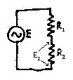
Consider a generator connected to two resistors in series. Call the resistors R1 and R2. If the generator produces an emf E volts, then the voltage across R2, call it E2, is equal to:
![]()
and the power P2 dissipated in R2 is equal to:
This value is a maximum when R2 = R1 and the power dissipated in R2 then becomes:
![]()
Now imagine that R1 is inside the generator itself. The above expression for the power P2 in R2 is the maximum which can be obtained by connecting a generator having internal resistance R1 to the resistance load R2. This is a very important result and is generally called the maximum power theorem. It demonstrates that the maximum power transfer can only occur when the two resistances are equal, and the generator and load are then said to be matched.
Resistances, Reactances, Impedances and Resonance.
What has been stated above is not only true for circuits containing pure resistance. In a circuit containing a coil and/or a capacitor, there will not only be the resistance of the coil to consider, but the reactances of coil and capacitor too. The reactance of a coil or capacitor can be thought of as the resistance of that component to alternating current (ac) and because the frequency of ac can obviously vary, the reactance of a coil or capacitor is frequency-dependent, or in other words, the resistance of a coil or capacitor to the passage of ac depends on the frequency.
The reactance is given the symbol X and is measured in ohms as is a resistance. The formulae for capacitive and inductive reactance are:
![]()
![]()
This begs the question, what is the real difference between a resistance and a reactance if both are measured in ohms? It is necessary in ac circuits to take account of the relative phases of voltage and current, and the difference between a pure resistance and capacitive and inductive reactances is one of phase. In a purely inductive circuit, the voltage leads the current (this is called a positive phase difference and is shown by +j) and in a capacitive circuit, the current leads the voltage (a negative phase difference shown by -j, j being the square root of -1). In a purely resistive circuit, there is no phase difference. In other words, the difference between resistive and reactive ohms is not real but imaginary (sorry about that.) Only resistances consume power, because for power to be consumed, the current and voltage within the component must be in phase. Reactances do not consume power (aside from any resistance they may have) but take it from the supply over part of a cycle and give it back over the rest. We might then amend our formulae to take account of this, and, whilst doing that, we can rename the 2pf bit, which appears with monotonous regularity, as the Greek letter w.
![]()
![]()
Inevitably in a circuit containing reactance there will always be resistance too. The combination of reactance and resistance is called "impedance". This too is measured in ohms and is given the symbol Z. If the coil or capacitor is efficient, the resistance can often be neglected (this is particularly true of capacitors) and the impedance is then numerically equal to the reactance. In other cases we must calculate the effect of the resistance, and in a circuit where there is a combination of significant resistance, capacitive reactance and inductive reactance, we must calculate the net result thus:
![]()
If there is more capacitive reactance than inductive reactance, the value of Z will be something multiplied by negative j; if there is more inductive reactance, Z will be something multiplied by positive j. Whenever the squares of the inductive and capacitive reactances do not come to zero under that square root sign, there is net reactance (shown as +j or -j) present in the impedance Z, and Z is said to be a reactive load.
Now, as we said above, only if the generator is suitably matched to the load will the maximum power be transferred. In the case of reactive loads, it is not enough for the generator to have the same impedance - the impedance Z of the generator must be the "conjugate" of that of the load - conjugate effectively means "equal and opposite" - and if the impedance of the load contains positive (inductive) reactance then the impedance of the generator must contain negative (capacitive) reactance of equal magnitude. [Psssst - this of course means that the load and generator together are resonant!]
Happily, this complexity is greatly reduced in the case of resonant tuned circuits as loads, because the reactances at resonance of capacitor and coil have equal and opposite phase differences and the load appears to the generator to be a simple resistance - the impedance Z of the tuned circuit as a whole is a pure resistance because the squares of the capacitive and inductive reactances under that square root sign sum to zero.
I have to confess a marked objection to the various statements sometimes seen that the reactances "cancel out". The reactances are not sentient beings! Coils and capacitors do not sit and conspire together to reduce their reactances to zero as the resonant frequency is approached! The reactances within each of the components are still very much present at resonance as is the relative phase difference due to them (if you were to take the components out of the circuit and measure their individual reactances at that same frequency you would see it) but the net phase difference across the input terminals becomes zero because phase differences, unlike reactances, do cancel and all the generator sees is a pure resistance. Hence the conjugate impedance required of the generator to get the most power into the load is also a pure resistance. As we saw in the paragraph above, a reactive load must be driven by a reactive generator having a conjugate impedance, and a vital consequence of the maximum power theorem is therefore demonstrated by tuned circuits themselves.
The Maximum Power Theorem inside Tuned Circuits.
Any tuned circuit at resonance obeys the requirements of the maximum power theorem. This is because, at resonance:
![]()
The impedances are "conjugate"; in terms of the reactances we know that XL = -XC. This equation corresponds to two physical realities:

1. The capacitor is fully charged and there is no current passing through the coil. This situation is unstable and the capacitor spontaneously discharges via the coil, creating a current in it which is linked with a magnetic field. The energy stored in the capacitor (potential energy) is exchanged for the energy associated with the magnetic field and flowing current (kinetic energy) in the coil. In other words,
![]()
The capacitor is the generator, and the coil is the load.
2. The current flowing in the coil is at a maximum and so is the associated magnetic field. The capacitor is fully discharged. Unfortunately, because of this, at this very moment the power supply fails. The situation is unstable. The current flow ceases momentarily, the magnetic field gradually collapses, and a current is induced in the coil, passes out of the coil and charges up the capacitor. Kinetic energy is exchanged for potential energy, the above formula is effectively written the other way around, the coil has become the generator and the capacitor has become the load.
Since the impedances of coil and capacitor are conjugate, the maximum power is transferred from (transferred from, not consumed by!) one to the other at the condition of resonance. If there was no resistance in the circuit, this exchange or oscillation would continue indefinitely because the current and voltage are out of phase in each branch of the circuit and no power is consumed; the damping and decrement would be zero and the Q infinite. Moreover, if the exchange of energy is attempted at any other frequency than the resonant frequency, the impedances are not conjugate and less than the maximum power will be transferred from one to the other.
Power is not consumed by the tuned circuit, except in any resistance which may be present, but is transferred from one component to the other and back again. This enables the tuned circuit to act as a sort of "accumulator" for radio frequency power and in a transmitter which is sending say 500W to the aerial and taking say 750W from the power supply, there may be over 7kW circulating in the tank circuit. The phase difference between voltage and current at resonance is equal and opposite in the coil and the capacitor and so at the terminals of the circuit there appears to be no phase difference at all. It's still there for each component - you just can't see it - the reactances don't "cancel", but the phase differences do. The tuned circuit at resonance appears to be a pure resistance because of the cancellation of the phase differences at the terminals, but it obviously is not exactly the same thing as a pure resistance because a resistive load by definition consumes power and converts it to heat, light, radio waves, mechanical energy etc. This is particularly evident in a parallel tuned circuit as shown, since at resonance the apparent resistance is very high (theoretically infinite).
This in fact tells us a lot about loads which are not at resonance but contain net reactance - a reactive load receives power from a generator for part of the alternating cycle, and gives it back over another part. Since the voltage and current are not in phase, power is not actually consumed except by the resistive component of the load. Such unconsumed, circulating power is called "wattless power" because it doesn't do any work. Electricity meters still measure it however, and you still pay the bill for it, so it is an excellent idea to minimise the wattless power taken by any electrical appliance, which of course we can do by cancelling the phase difference present at its input terminals. This is called "power factor correction", is generally achieved by connecting appropriately rated capacitors across the mains input to the appliance, and a purely resistive load on the mains supply has a power factor of one, meaning there is no wattless power for which you are being charged. Not only is this advantageous to the consumer, but it would be a disaster for the power company if the distribution system was feeding a huge reactive load with massive out of phase components (remember the maximum power theorem!) and power companies require that all large loads are power factor corrected. All appliances which you buy and which have a significant reactive component to their load characteristics are power factor corrected by the manufacturer, so please don't try "tweaking" them!
The next installment will examine the meaning of Q and how to achieve an impedance match by inductive coupling.