The Spark Transmitter. 3. Maximising Power, part 2.
"What may seem to the uninitiated a simple explanation, may appear to the expert as a most round-a-bout way of stating the ideas; the technical words are the short cuts."
C.R. Gibson, F.R.S.E.
Unloaded Q and Loaded Q.
The parameter Q has been mentioned several times and it is now appropriate to consider what is meant by Q. The definition of this quantity is simply the ratio between reactance and resistance, or in other words, wattless power divided by in-phase losses. It can also be expressed as the amount of power circulating in a resonant circuit divided by the amount of power which must be added per cycle to keep the oscillations at constant amplitude. There is a variety of definitions therefore, but all with the same underlying meaning; Q is a measure of efficiency and is frequency-dependent.
Unloaded Q refers to the Q of the coil, capacitor or tuned circuit itself with no other factors considered. This might reasonably be the Q value measured on a Q meter, or the Q of a Tesla secondary operated without ionisation of the air or spark breakout.
Loaded Q might refer to the same component or circuit, but now under operating conditions such that it is expected to be coupled in some way to a resistive load in which power is being dissipated. Thus it could be the Q value of a valve transmitter output tank circuit when that transmitter has been properly adjusted to feed an aerial, or, what is effectively the same thing, the Q of a Tesla coil primary circuit when the coil is in operation and sparks are being drawn from the secondary.
The difference comes about very simply because coupling a tuned circuit to a load reflects the resistance of that load into the tuned circuit (how much depends on the coupling). If Q is the reactance divided by the resistance, then if the resistance goes up, Q comes down. In fact, operating a spark transmitter or Tesla coil in the unloaded condition is asking for serious trouble: if the primary circuit has nowhere to dump its power which might come about through serious mistuning, all of that "output" will remain in the primary circuit, causing severe overheating at the gap with damage to the sparking surfaces and probable breakdown of the capacitor insulation. The same is true of valve transmitters, where the circulating output power results in a badly overheated anode, and in modern semiconductor circuits where it results in dead transistors if the protection circuitry isn't quick enough. The efficiency of an output tank circuit is simply:
![]()
and the relationship between the voltage, power and QL of a tank circuit under pure sinusoidal conditions is given by:
![]()
where P is the power, w is 2p times the frequency, L the tank circuit inductance and QL the loaded Q.
Thus high unloaded Q, QU , is necessary to ensure low losses in the components themselves, and low loaded Q, QL , to ensure that there is not a build-up of power circulating in the tuned circuit, but is transferred to the load and thereby to ensure reasonable overall efficiency. Simply adjusting the coupling between the primary and secondary will vary QL within reasonable limits. (More about coupling and the coupling constant k later.) Tight coupling gives low QL, loose coupling gives high QL. In a transmitter, this value of QL matters for another reason, namely that it gives added harmonic suppression and transmitters generally compromise with a QL value of between say 5 and 15. Lower than 5 and the harmonic suppression suffers. Higher than 15, and the components in the tank circuit begin to get hot.
The reason for this is not hard to see. If Q is defined as wattless power divided by losses, then the losses are not restricted to heating losses - a tank circuit feeding an aerial has a power loss to the aerial, and the wattless power is that being transferred between the coil and capacitor (remember the maximum power theorem inside tuned circuits). If QL is 15, what this means is that there is fifteen times as much circulating, wattless power as there is being delivered to the aerial. There will, of course, be fifteen times as much heating loss as for operation with Q = 1 because whatever the circulating current, it will also pass through whatever resistance is present in the tuned circuit and being in-phase in the resistance, will produce i2R losses. A 500W transmitter at full output may take 750W from the supply if it is efficient; if the loaded Q of the tank circuit is 15, then there will be 15 x 500 = 7,5kW circulating as wattless power in the tank circuit. Likewise, in a Tesla secondary there may be a very large wattless power circulating, built up over a number of cycles, which is periodically dumped into a large spark as in-phase power as soon as the wattless power accumulated is sufficient to bring about ionisation of the air.
In a spark transmitter or Tesla coil, increasing the loaded Q up to this point restricts the power transfer to a narrower range of frequencies and if the balance is right, the maximum current in the aerial (or Tesla secondary) will increase, yielding better results, always assuming the primary voltage developed is within the primary capacitor rating! But it isn't quite as simple as that, because the value of QL also sets the level of circulating current in the coil and hence the magnetic field and hence the efficiency of power transfer; QL values less than about 4 are quite difficult to extract sufficient power from without an excessively high coupling constant and close proximity of the coils. The really big (read megawatt) transmitters obviously cannot afford to use a high loaded Q in the tank circuit and operate with QL of 3 or 4 at most; in such cases, special techniques are employed to obtain efficient coupling and good harmonic suppression. Let's look at an example of valve technology (modern transistor technology tends to do things differently for a variety of reasons) in which a valve output circuit is delivering power to a transmission line of 50 ohms impedance. Let us assume it transmits on 200kc/s and that we want to design for a loaded Q of eight.
Firstly we decide on the reactance of the tuned circuit components. This is simply QL times the transmission line or load impedance, so it's 8 x 50 = 400 ohms. Now using the standard formulae backwards we calculate the values of L and C at 200kc/s which will give 400 ohms reactance:
![]()
![]()
These values of L and C will not only resonate at 200kc/s, but when coupled to a load of fifty ohms via a link coil will allow a loaded Q of eight to be readily achieved without the output link being so close that there is a danger of high tension flashover. This evidently has serious application to Tesla magnifiers, as we shall see later.
Measuring Q.
Use a Q meter! These occasionally turn up at ham radio rallies. If you have an oscilloscope and a signal generator (couple both very loosely to the tuned circuit) you can find the resonant frequency and the two frequencies, one either side of resonance, which give 0.707 times the voltage maximum at resonance, call them f0 for resonance, f1 and f2 for the lower and the higher frequency respectively (the other coil - primary or secondary - must not be in the vicinity when this measurement is made, i.e. the measurement is to be made on the uncoupled system). The unloaded Q is then equal to the resonant frequency divided by the bandwidth:
![]()
Accounting for resistance.
In the real world, we must modify the equation we had for a tuned circuit which described the energy stored in the capacitor as being equal to that in the coil, so as to include the losses due to resistance. We now have:
![]()
or, rearranging:
![]()
It is now possible to see the importance of high unloaded Q in the primary inductance of the spark transmitter. (This of course applies also to the secondary.) The potential energy stored on the capacitor is divided between the kinetic energy of current and magnetic field in and around the coil on the one hand (wattless power) and the heat energy dissipated in the resistance (in-phase power) on the other. But there's more to it than that. Remembering that the resistance is proportional to the number of turns on the coil (number of turns multiplied by p by diameter equals length of conductor) and the inductance is proportional to the square of the number of turns, as we add turns to the coil, the inductance increases more rapidly than the resistance. In other words, coils of high inductance tend to be more efficient than coils of low inductance because the ratio of inductance to resistance is higher (at a given frequency this means that QU is higher) and hence the division of energy between inductance and resistance favours the inductive kinetic energy rather than resistive heating losses. This inductance helps overall efficiency when you consider that there is also the resistive loss associated with the primary spark gap to be taken into account.
It was often noticed by radio amateurs after around 1912 (when, following the loss of the "Titanic" they were banished to wavelengths shorter than 200 metres / frequencies higher than 1.5Mc/s) that at these higher frequencies it was difficult to get a spark transmitter to operate efficiently because of the need to use small coils, and lead lengths had to be kept very short to ensure that most of the inductance was in the coil (which being coupled to the aerial, would do some good) and not in the interconnections where it would be wasted. Spark transmitters and Tesla coils alike benefit from plenty of inductance in the primary circuit to help offset the resistive losses in the spark gap. However, there is indeed a limit to the usefulness of more turns. As the inductance goes up, the current goes down, and the resistance of the gap is inversely proportional to the current.
As a coil acquires more turns, so the radio frequency resistance of the coil is increased over and above that due to the additional length of wire by the "proximity effect" between all those turns, which tends to reduce the cross-sectional area of the wire over which the current can flow. Then there is the "skin effect" which constrains high frequency currents to flow on the outside of the conductor. This is more noticeable with thick wires than thin wires, and the ratio between the rf resistance of a thick wire and its dc resistance is likely to be large, resulting in the curious fact that there is an optimum wire size for a given size of coil and a given resonant frequency. So in practice there is always an upper limit to which inductance of a coil can be increased, for a given frequency of operation, size of wire, spacing, and overall length and diameter, before the efficiency starts to fall off. Happily, in the case of primary windings, this limit is seldom approached. With Tesla secondaries, 600 - 2000 turns may prove useful before anything untoward is noticed, and this will vary widely according to the variables stated above.
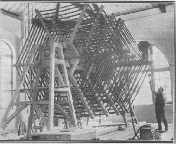
The photo above shows a low loss transmitting inductance at the Rugby station in the early 1920s. The scale of things can be gauged by the two workmen.
The proximity effect is very hard to predict, but the skin effect is much simpler. In copper wire at 20°C, the skin depth in centimetres is given by:
![]()
If you imagine a circular wire, the skin depth is represented by a thin ring around the circumference and all the current may be thought of as flowing in it. This is not the physical reality; the current actually decreases exponentially with depth and there are major phase changes too, but the skin depth is the thickness of a ring in which all the current could flow and give the same observed resistance, assuming no proximity effect (which sadly is only true if there are about ten wire diameters between turns!)
The skin depth is proportional to the square root of the resistivity of the wire and resistance wire accordingly suffers less from the skin effect than copper, since a resistance wire must be much thicker than a copper wire at a given frequency before the effect becomes noticeable. Accordingly, where wires are thick enough to exhibit skin effect, there is less difference between the rf resistance of copper and resistance wire than the dc resistance difference between the two might lead you to expect, since the lower thickness of the copper skin in which the current is flowing tends to be compensated for by the greater thickness in which the current flows in the resistance wire.
The resistance of copper wire at 20°C of diameter d centimetres in ohms per centimetre at radio frequency is:
![]()
The solutions to the problems of proximity and skin effect were worked out by a number of early wireless technology researchers, and originally it was German wireless engineers who, around the time of the First World War, came up with the solution called "litzendraht". Litzendraht, or litz, consists of a number (anything from three wires to several thousand) of individually insulated wires braided together, the individual wire diameter chosen such that the skin effect is negligible in each wire, and braided together in such a way that each wire has a reasonably equal share of the inside and outside of the composite wire so formed. For the sort of frequencies commonly encountered in Tesla coils, 0.08mm (44swg) is a fair compromise and coils having an extremely high Q can be wound with litz made up from 44swg wire. It is astonishingly expensive to buy (currently around £12 for one ounce) and for anything except the small coils used in wireless work, it is best to "roll your own" even if that means that the optimum braiding is unlikely to be achieved. Whilst it is now extremely expensive, using litz has become very much easier since wires ceased to be enamelled with real enamel. In my Father's day, litz of 50swg was in common use for frequencies around 1-2Mc/s, and the enamel had to be carefully scraped with a sharp razor blade from each 0,025mm strand before it could be soldered, resulting in a certain amount of "litz rage" when large numbers of wires had to be treated - and broke. Small diameter litz of more than 27 strand was accordingly none too popular. These days, with plastic insulation, you just solder it using a hot iron which burns clean through the covering.
However, Q in the secondary can be made sufficiently high for practical purposes without the complexity of litz simply by using wire of the optimum thickness; though a coil can always be made more efficient at frequencies under 1Mc/s by using litz, it can become critical on the efficiency of the braiding of the strands and the insulation which spaces each strand. Calculations of optimum thickness of a single strand were yet again done around the time of the First World War and books on wireless technology of pre-WW2 vintage often give ideas and references should you be keen to try. A particularly valuable paper on this whole topic was written by Professor C.L. Fortescue and published in the Journal of the Institute of Electrical Engineers, pp 933-943, 1923. This, and the references in it, and more particularly the criticisms in the discussion at the end of the paper itself, are a good guide to the design of coils - and also a guide to the pitfalls.
Whilst the skin effect is essentially conquered by these techniques, proximity effect can only be overcome by trial and error spacing of the turns. It often transpires that the losses associated with the proximity effect are more acceptable than the extra length of wire and extra resistance if the turns are to be spaced, and this is particularly the case with large diameter single wires. With wires of optimum diameter or litz, spacing is usually effective, but litz is in a sense automatically spaced because of the insulation around each strand and the overall covering, usually silk (real or artificial).
Another invention from this same era was the ferrite core. Ferrite cores concentrate the magnetic field produced by a coil into a small volume, and a greatly increased inductance can be obtained from a small coil by using a ferrite core. Since the inductance has been increased without significantly increasing the resistance (you must be careful to provide a small amount of clearance between the ferrite and the coil or the ferrite will increase resistive losses) the Q of the coil improves dramatically, values in the high hundreds being common. Unfortunately, ferrite cores in Tesla coils are generally not a good idea, and this for several reasons:
The coil response now extends down to dc and is no longer confined to the resonant frequency alone! Basically, the ferrite core reduces leakage inductance and increases the coupling constant k to something a lot closer to one. This makes for an exceptionally vicious pulse transformer which responds to all oscillating magnetic fields regardless of frequency, rather like an iron cored audio transformer and with similar characteristics of broad frequency response with a high frequency hump due to resonance at the top end. Not only do you get the benefits of the decaying oscillatory sinewave rf discharge, but you get the massive wallop from the initial dc pulse out of the capacitor. Whereas with a small air cored Tesla coil of say ten watts it is perfectly safe to take the spark discharge into a piece of bare metal held in the hand, if it is ferrite cored the result will be extreme pain if not risk to life. I found this out the hard way, fortunately through the handle of a well-insulated screwdriver. Though separated from the metalwork by one inch of clear plastic, I could feel every single spark like a stinging slap on the palm of my hand. Mercifully, I was expecting trouble and took the precaution of using the screwdriver; I dread to think of how it would have felt if I had been using a bare piece of metal instead. The conventional, air cored coil I usually used with the same power source gave a spark which I could take to a key or metal rod with nothing felt.
The ferrite core has a saturation limit, or in other words, for a particular frequency there is a limit to how much power you can couple through each cubic inch of ferrite. The more powerful the coil, the more ferrite is needed and this, like litz, is not cheap.
Ferrite is not a perfect insulator. Some grades are actually of quite low resistance, only a few hundred ohm-centimetres. In my experiments I simply potted the ferrite (which was a high resistivity grade, being one inch diameter interference suppression beads intended for slipping over half inch diameter cable) in beeswax and wound the coil on a thin former over that, and there was no trouble with insulation breakdown. That's all well and good for a low-powered baby coil of ten watts input, but I wouldn't expect it to hold for a kilowatt!
Coils using ferrite cores are not a good idea for these reasons. If you simply must try it, make a baby coil with not over ten watts input, and under no circumstances try to take the discharge into a bare piece of metal in your hand, or I promise you will regret it. This caution is of less importance if the source is a sinusoidal generator rather than a spark transmitter.
The next section looks at the vexed question of the ideal conductor for radio frequencies.