The
Quick & Dirty VTTC
Via
the internet, I discovered that to my surprise and delight, the
"Ionophone" referred to elsewhere on these pages is very
far removed from defunct. Several versions have been produced around
the world by different manufacturers. One man, Ulrich Haumann, even
went so far as to build his own. He in turn inspired others to
follow suit. It was from Ulrich's plans that I swiftly (and I mean in
2-3 hours and very leisurely at that) threw together the coil which
appears here. First, the circuit diagram, which is a little changed
since I have at present no modulation capability for the plasma:
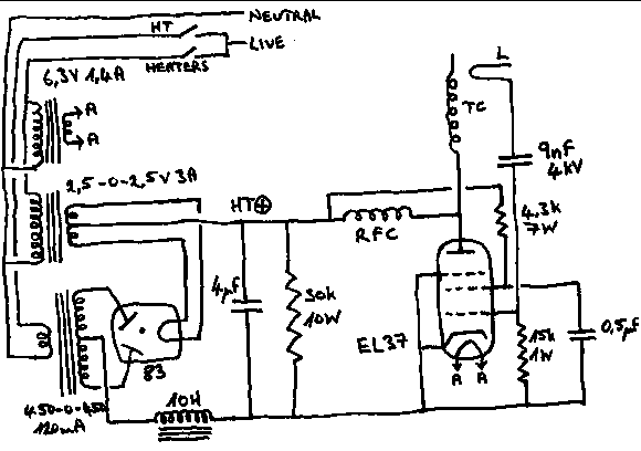
Ulrich
reported minor problems with the rf choke RFC in the above. With a
little experimentation I found that the inductance of this component
is not important, but that if a second Tesla coil TC is wound, this
serves perfectly as the choke. This Tesla coil/choke should be say
25-40 turns of thick (0,9mm - 2,2mm) wire wound to a diameter of 25 -
35mm, the thing is completely non-critical, so long as both are the
same. Apparently the self-resonance of this choke at the operating
frequency performs admirably to keep the oscillations from escaping
into the power supply (and no, the HT side isn't earthed to anything,
I simply threw it all together breadboard fashion!) The first choke
I used was 164uH and physically rather large. It can be seen lying
horizontally behind the Tesla coil and valve (EL37) which are at the
front of the layout. It was not resonant at the operating frequency,
and though it is made of 1,6mm wire and carries only 160mA, it got
warm in use! The second Tesla coil I wound, which I used in place of
this choke, remains stone cold. A later photo shows this component.
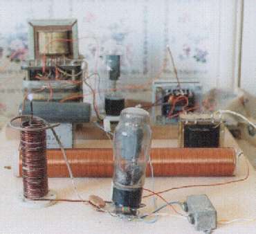 At
the rear left is the HT transformer, on top of which is perched the
10H choke, which is essential when using a mercury rectifier. This
valve, type 83, is to the right of the HT transformer, centre rear.
At the right rear with its LT centre tap sticking straight up is a
homebrew filament transformer for the 83. Despite only putting out
5V at 3A, this secondary needs high voltage insulation because it
forms the positive HT terminal and can be at up to 400V. In front of
that, right midfield, is the LT heater transformer (6,3V) for the
EL37. Left midfield is the 4uF smoothing capacitor on top of which
is a very large 30k resistor. The front row shows the Tesla coil on
the left, atop which is the plasma, barely visible against a steel
band of the HT transformer (bad siting on my part for the photo.)
Near the valve base of the EL37 to the left is a parallel pair of
4,5nF 4kV ceramic capacitors. The value isn't very important, but a
high voltage rating is, as the "hot" side is connected to
the loop L, seen at the top and outside of the Tesla coil as a thick
brown wire. In front of the valve base is the 15k grid resistor
(read it right to left - brown, green, orange) and to the right of
the valve base the 0,5uF screen bypass capacitor. The white blob
apparently hovering in mid air at the left shoulder of the EL37 is
the screen resistor of 4,3k (actually a 3,3k resistor in series with
a 1k which is out of sight).
At
the rear left is the HT transformer, on top of which is perched the
10H choke, which is essential when using a mercury rectifier. This
valve, type 83, is to the right of the HT transformer, centre rear.
At the right rear with its LT centre tap sticking straight up is a
homebrew filament transformer for the 83. Despite only putting out
5V at 3A, this secondary needs high voltage insulation because it
forms the positive HT terminal and can be at up to 400V. In front of
that, right midfield, is the LT heater transformer (6,3V) for the
EL37. Left midfield is the 4uF smoothing capacitor on top of which
is a very large 30k resistor. The front row shows the Tesla coil on
the left, atop which is the plasma, barely visible against a steel
band of the HT transformer (bad siting on my part for the photo.)
Near the valve base of the EL37 to the left is a parallel pair of
4,5nF 4kV ceramic capacitors. The value isn't very important, but a
high voltage rating is, as the "hot" side is connected to
the loop L, seen at the top and outside of the Tesla coil as a thick
brown wire. In front of the valve base is the 15k grid resistor
(read it right to left - brown, green, orange) and to the right of
the valve base the 0,5uF screen bypass capacitor. The white blob
apparently hovering in mid air at the left shoulder of the EL37 is
the screen resistor of 4,3k (actually a 3,3k resistor in series with
a 1k which is out of sight).
One
important feature of the circuit is that the heater/filament volts
can be switched on independently of the HT volts. With a
semiconductor rectifier this doesn't matter, but with a mercury
rectifier it is vital, as mercury rectifiers are easily damaged
electrically, something rare amongst valves. The filaments must heat
for long enough to evaporate any mercury droplets from within the
electrode structure before the HT volts go on, or there will be a
flashover with damage to the valve. "The book" says thirty
seconds. Mercury rectifiers are getting hard to find, and I give
mine two minutes. Even so, I have had the occasional blue flash at
switch-on, fortunately with no damage to date.
So
why use them? They're expensive, delicate mechanically, delicate
electrically, generate waste heat, generate interference, take up space, demand a separate
and very well insulated filament transformer with a centre tap (this
centre tap actually matters if you want them to last long) demand a
choke coil to restrict the peak amperage drawn, require you to wait a
while for the filament to heat before you can switch the main power
on and when they finally give up, disposal is a real problem (which
so far I have not had to face) as you obviously can't throw them in
the household rubbish (though I bet that's exactly where most of them
went years ago.) So why? Well, they're a lot more interesting to
look at than a 1N4007. Even an exploding 1N4007 isn't half as pretty
as a mercury rectifier.
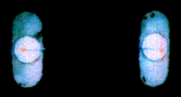 The
blue glow from the mercury vapour inside the two anodes of the 83
contrasts nicely with the bright orange filaments, though the
filaments haven't really shown up too well in this photo. The
unaided eye sees them much better.
The
blue glow from the mercury vapour inside the two anodes of the 83
contrasts nicely with the bright orange filaments, though the
filaments haven't really shown up too well in this photo. The
unaided eye sees them much better.
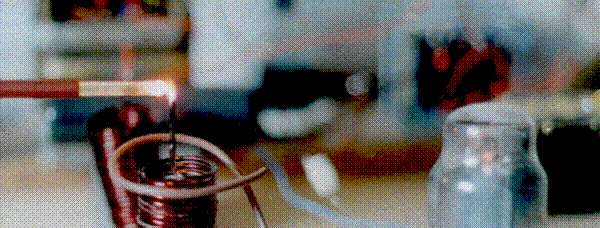
The
plasma has to be "ignited" by allowing a well-insulated
screwdriver to brush the tip of the Tesla coil, the stray capacitance of
the metal being enough to incite the arc to strike. On no account
should a bare piece of metal be used, as not only the radio frequency
power but also the dc HT positive will short to earth through the
object (and you if you are holding it). On the other hand, a
well-insulated object can be inserted into the plasma. Here, a glass
tube (supported on a rubber tube, supported on the well-insulated
screwdriver tip) is being heated to white heat by the plasma. The
glass becomes electrically conductive, and a yellow rf arc is drawn
to the glass, though the yellow doesn't show up too well against the
brilliant white-hot glass:
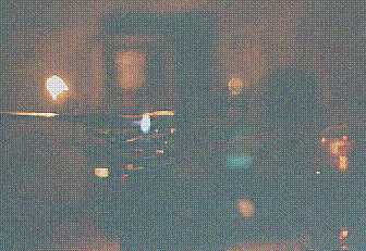
Out
of focus, behind the Tesla coil and at an angle is the second Tesla
coil which is used as the rf choke, now replacing the very large
horizontal choke shown in the previous shot. Whilst a slight glow of
the EL37 heater is barely visible, these things are much better seen
in the dark:
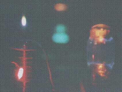 The
plasma is now clearly visible as a bright white "flame" to
the left. To the eye it appears blue with a green tip from the
copper wire. Far right is the orange glow of the EL37 heater, and to
its left a blue light from the 83, plus an orange-red blur above
from the 83 filament. The blue fluorescence of the
EL37 glass (due to very high vacuum in the valve) is also seen,
thanks to another photo-shoot with faster film (Jessop's 200ASA). Mid-way up the coil is the bright light of a neon bulb held nearby, the gas is ionised by the rf field of the coil.
The
plasma is now clearly visible as a bright white "flame" to
the left. To the eye it appears blue with a green tip from the
copper wire. Far right is the orange glow of the EL37 heater, and to
its left a blue light from the 83, plus an orange-red blur above
from the 83 filament. The blue fluorescence of the
EL37 glass (due to very high vacuum in the valve) is also seen,
thanks to another photo-shoot with faster film (Jessop's 200ASA). Mid-way up the coil is the bright light of a neon bulb held nearby, the gas is ionised by the rf field of the coil.
 In this photo, a small filament lamp connected across a few turns of wire is being held at the top of the Tesla coil. Rf energy from the Tesla coil is then induced in the coil across the lamp and lights it, demonstrating the presence of inductively-coupled energy. The lamp used to perform another trick, until I got it too close and cooked it . . . the gas in the lamp would light up blue and it was possible, once the filament had lit (electron emission produced thermionically helps ionise the gas filling) and the gas had ignited, to raise the lamp with its coil just above the plasma flame, rotate the plane of the coil on the lamp through 90 degrees to reduce inductive coupling to near zero, and the blue glow from the gas would remain due to capacitive coupling of rf from the Tesla coil. Unfortunately, as I said, I got a bit carried away with this neat trick and it wouldn't do it for the camera! Another shot on Jessop's 200ASA.
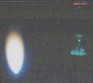 Here's a closeup of the plasma flame, on Jessop's ASA200, the blue glow from the 83 is visible in the right background. This has been an interesting illustration of the differing sensitivities of the eye and film to different wavelengths at low levels of illumination. The plasma flame is distinctly blue to the eye, but less so to the film, also the tip of the flame is greenish, whereas the film sees it as yellow! I've also noted that weak Tesla streamers from the induction coil setup elsewhere on these pages are very blue to the film, but purple to the eye! This coil has now been dismantled and the bits recycled for other experiments. Most of my projects tend to go that way, only a very few things end up as keepers. It's interesting to note that, despite the resonant frequency of this coil being around 29Mc/s the amount of radio interference was low - nice one for the law of conservation of energy - you can either radiate it as radio waves, or use it to ionise the air and make it hot, but not both at once.
All photos Olympus OM1 plus Kodak Gold ASA100 unless otherwise stated.
Back
Homepage