The
Quenched Spark Gap
"...and
here's the practice o' it."
Unknown
The
quenched gap, as popularised by Telefunken, was a great success owing
to the very high rate of switching which lent increased efficiency to
their transmitters. It was said that a 500 watt Telefunken set with
its quenched gap could outperform a Marconi set of 2.5kW with its
rotary gap, and this was mostly down to the efficiency of the
Telefunken gap, an early and poor quality illustration of which was
included in "Alternator, Arc and Spark."
I
decided at the outset of my attempt to replicate a spark transmitter
that I wanted to use a multi-plate quenched gap and hence had to set
about making one. At the time, I could not obtain copper sheet in the
sizes I wanted, nor copper rod at all, so the whole thing was made
from brass. The electrical and thermal conductivities of a metal are
related through the Wiedemann-Franz law which states that the ratio
of these conductivities is a constant, independent of the metal and
varying only with temperature. Regarding electrical conductivity, the
difference is not enough to cause concern as the skin effect gives
some degree of compensation (as will be shown later) and the
periphery of each gap is large, but regarding the thermal
conductivity of brass I was a little concerned that the inferior
thermal properties might be the ruin of my plans. I need not have
feared. For the relatively short time that I fire the thing up, the
gap never gets more than tepid at the most; however, had I the choice
and was starting over again I would use copper, although it is much
less pleasant to machine. Aluminium would also be a good choice for
the cooling flanges, though probably not for the gaps.
The
cooling flanges are about 15cm/6 inches in diameter and are made from
1,6mm thick brass sheet. The eight flanges had to be cut by hand
using a 52 tooth-per-inch piercing saw with occasional lubrication
with cutting fluid. This took a long time as may be imagined, each
flange having a circumference of 47cm/18¾ inches, all eight
amounting to sawing a line 3¾ metres/12ft 6 inches long, and
consumed several weeks' worth of evenings and weekends, with
considerable wear-and-tear on elbow and wrist joints and many tired
fingers! The blades are fortunately not expensive, which is just as
well as each blade lasted little over one flange.
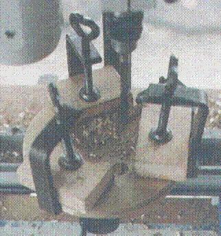
The
next stage was to mount all eight flanges together, drill a 1/8 hole
through the centre of all eight on a friend's drill press (thanks
Dennis, G7OGN) pin them to prevent their moving relative to one
another and attack the edges with a file until they were all about
even; an electric drill with carbide roughing disk speeded this
process considerably, but flying burrs necessitated good eye
protection with polycarbonate safety goggles. Following the smoothing
of the edges and removal of many sharp burrs with suitable care to
avoid impaled fingers, not always successfully, the eight flanges
were mounted together on the trusty Unimat 3 and three holes drilled
at 120°, each hole starting out
one eighth in diameter, and by progressive stages being enlarged to
half an inch, pinning these holes in turn to prevent rotation of the
flanges between or during drilling operations. Drilling these three
holes necessitated keeping one hand on the Unimat motor (for those
who are not aware, the Unimat 3 motor is not continuously rated) and
switching off when it became too hot to hold, which was often. This
was a long, slow, laborious business, even with plenty of cutting
fluid. That brass sheet is tough old stuff, and there's 8 x 1,6mm =
12,8mm (a bit over half an inch) of it in total to be got through.

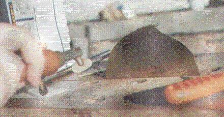
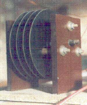
The
next job was by way of light relief. The brass cooling flanges were
now supported by nailing them very loosely to a piece of scrap wood
through their centre holes and having masked their centres (where the
electrical contact with the gaps would be made) spray painting them
with black matt barbecue paint. There are chemical methods for
blacking brass, which I would use if I had access to the chemicals
(my PhD is in chemistry!) but sadly I didn't at this time so had to
make do with paint. If the authenticity bug bites very deeply, I may
just strip all the paint off and do the job properly, but I doubt
even I could tell much difference.
Other
tasks performed, but not photographed, were:
the
cutting and drilling of end plates from Tufnol paper/phenolic
composite (takes the edge off a plane in minutes, giving the blade
the appearance of having been attacked by a file)
this composite being chosen as it looks very like Bakelite;
turning, cutting with
a die, hardening and tempering the pressure screws and their
mounting nuts, which are used to compress the gaps tightly together;
turning thick fancy
brass washers to place under the nuts of the tension studding;
cutting and trimming
Tufnol tubing to act as insulators over the studding, the studding
and insulator passing through the three half inch holes in each
cooling flange;
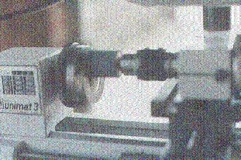
sawing
with an eighty-teeth-per-inch piercing saw blade mica washers out of
two inch mica disks 1/16 thick. These had to be smoothed down to a
flat, parallel profile and this was very tedious indeed, being
accomplished by a combination of rubbing the washer against a piece
of sandpaper stapled to a board (and losing half the fingerprints
from the tips of my fingers in the process - ouch! - and the blood
on the mica doesn't help its insulating properties either) and
holding the washer in the three jaw chuck of the lathe, which was
free to rotate, and bringing up upon it a small grindstone spinning
at 4000rpm in the drill chuck (shown above) - unfortunately the soft
mica rapidly plugs the grain structure of the grindstone. I started
with forty disks and ended up with about fifteen washers between
1-1,1mm thick from which to select the best ones for the gaps -
obtaining complete uniformity was impossible;
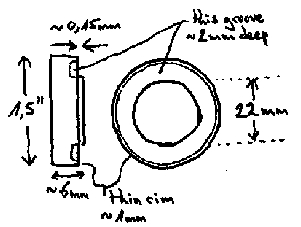
turning
twenty brass disks, one and a half inches diameter and around a
quarter of an inch thick to act as the electrodes for the ten gaps.
Ten gaps was the number selected on the basis of 1kV per gap. This
operation was photographed but unhappily the flash unit mistimed and
the fault was not noticed until the job had been done and the film
then developed. A sketch of an electrode disk is appended. The
recessed groove was cut later as a result of experience and it very
effectively prevents the spark from "walking" its way
through the insulating washers. The height of the protruding
sparking surface was matched to the washer giving an overall gap
length of around 8mm for 10kV, or 0,8mm/ 1/32 inch per gap. The rim
was progressively reduced in thickness in order to increase the
pressure applied to the washers (pressure = force / area) and
improve the sealing, but obviously the strength of the brass limits
the extent of this thinning process. These gap electrodes were
silver plated by a local firm on the basis that a chapter on spark
transmitters in an old book I have says the electrodes were silvered
- the silvering lasted mere minutes under normal conditions of use,
so the electroplated layer of ten microns was obviously far too
thin. The finished gaps do look nice though.
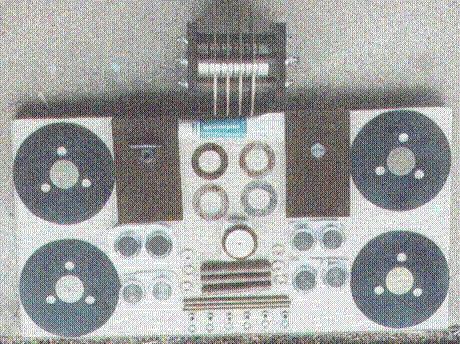
The
photograph above shows one completed rack of five gaps at the top,
comprising four cooling flanges and ten silvered brass electrodes,
each pair of electrodes separated by a mica washer, barely visible as
five thin black vertical lines between gap electrodes. The end two
gap electrodes have no cooling flange and are accordingly made much
thicker; contact to these is made by 4mm radial holes into which a
plug can be inserted. Below the completed rack lie the components for
its partner. The blue thing at the top centre is a tube of silicone
high vacuum grease with which to help seal the gaps to the washers
(not entirely successful.) Immediately below the tube of grease are
four mica washers and to the left and right of them the two Tufnol
end plates. The Tufnol plate to the left has the pressure screw
resting horizontally just above the captive nut through which it
normally passes, whilst the right hand plate simply has a hardened
bearing for the stack of gaps to rest on. The four cooling flanges
are on the outside to left and right. Below each Tufnol plate are
four gap electrodes. Below the four mica washers is an assembled gap
consisting of two electrodes (one invisible underneath) and a mica
separating washer, the rim of which can be seen. The mica washers are
translucent and in operation, dim light from the discharge can be
seen to cover the whole area of the discharge surface. A small hole
is visible on the back of the upper electrode. These were machined in
pairs, one of each pair having a hole, the other having a pin, and
these pins are pushed through similar holes in the centre of the
cooling flanges and the partner electrode then mounted on the other
side of the flange. The centre holes in the flanges do not really
show up in this photo, but they do on the picture showing the flanges
mounted for spraying as there is a nail through the black masking
circle on each one. The spacing of the three half inch holes on the
cooling flanges is such that when the three Tufnol insulating tubes
are passed, with their tension studding, through the flanges, the
tubing just clears the two inch diameter mica washers. Below the
mounted gap are the three horizontal insulating Tufnol tubes, to the
right and left of which are the six (total) fancy brass washers.
Below the three tubes are the three lengths of studding and below
them, six nuts and six plain washers. The studding, plain washers and
nuts were purchased. Everything else was made. In all, this project
occupied around four months of spare time. Around a kilo of scrap
brass was produced, a small mountain of scrap mica, and large numbers
of piercing saw blades and Unimat drive belts were broken.
These gaps
are NOT for sale!
The next
section looks at some questions of efficiency.
Back
Homepage