So what exactly is a Tesla Coil?
"But Captain! Ye cannae change the laws o' physics!"
Chief Engineer Scott, USS Enterprise
There remains nagging away in the back of the mind the idea that the exact mechanism of operation of a Tesla coil has still not been fully disclosed. This bothered me not at all to begin with, as my interest lay with the spark transmitter and the Tesla coil was a mere dummy load and nothing more. Eventually, however, I had to concede that the blasted thing would not leave me in peace until I had got to the bottom of it. I pondered for an excessive amount of time over this, until gradually the concept began to emerge from the murk. All this Tesla coil stuff seems vaguely familiar from somewhere . . .
I can remember from 25 years ago, one of my chemistry teachers asking the class "What would happen if you put a bottle of electrons in the middle of the lab?" He then proceeded to give the wrong answer, that everything in the lab would immediately rush towards the bottle because of its net charge. Actually, you and I know the right answer to that question. The electrons have so much less inertia than everything else in the lab that it is the electrons which do the moving, bursting out of their bottle and rushing in all directions towards the induced positive charges on the surface of each earthed object in the vicinity. The important thing of course is the charge q, i.e. the number of electrons stuffed into that bottle. There are 96500 coulombs in one faraday of electricity, and each coulomb is equal to 6,24 x 10¹⁸ electrons. The more electrons in the bottle, the greater the repulsive force developed between them, the greater the induced charges in the surroundings, and the greater the attractive forces between the electrons and their surroundings.
The Tesla coil, it turns out, is very closely related to another high voltage machine, the Van de Graaf generator. Perhaps it would be more appropriate to state that relationship the other way around, since the Tesla coil predates the Van de Graaf by at least half a century.
Excluding the rotary spark gap, if any, a Tesla coil is a Van de Graaf generator with no moving parts. The rotating insulated belt which carries the unidirectional charging current in the Van de Graaf is replaced, in the case of the Tesla coil, by the rotating vector of the sinusoidal oscillation which carries the bidirectional charging current. The essential physics of the charging of isolated electrodes is the same for both. The dielectric breakdown of air is but little different, a relatively minor modification being required on going from dc to low frequency ac, to high frequency ac. The Van de Graaf generator is simply a dc version of the Tesla coil. Whereas it has been found progressively more difficult to increase the charging current of Van de Graaf machines to much above a few milliamps, the charging currents associated with Tesla coils are measured in amps. This is because the charge q on the top electrode makes the journey from earth and back again in microseconds, and current is simply the rate of charging, dq/dt. As the frequency is reduced, the current for a given charge falls, and this helps to explain why Tesla coils tend to get more efficient as the frequency drops, as the resistive in-phase i2R losses for the circulating, wattless power in the secondary system (and primary) are generally smaller. Since the current falls with frequency, it also explains why the charging current for a Van de Graaf of the same top electrode capacitance is so much less at dc than for a Tesla coil at ac.
Actually, this is not the whole story and in fact there is something unexpected about the role of resistance during the exchange of energy between the primary and secondary. Whilst resistance certainly is important in causing losses in circulating, wattless power in a tuned circuit, in the electromagnetic transfer of that power between circuits, we have a different situation. The losses in connecting a charged capacitor to an uncharged capacitor via a resistor are independent of the resistor value, and depend only on the relative capacitor sizes and the magnitude of the charge. The efficiency of the transfer of energy between primary and secondary therefore depends very little upon the efficiency Q, provided it is enough to ensure magnetic coupling which will be the case if QL is at least five.
It is very unfortunate that the symbol Q can have two meanings, either a measure of the efficiency of a capacitor, coil or tuned circuit, or alternatively a quantity of charge in coulombs. In what now follows, Q and q are both amounts of charge. The following derivation is due to the late Professor Cotton of Nottingham University.
If
C1 is charged to a voltage V1 and a charge Q is
stored on its plates, and C2 is uncharged, i.e. V2
= 0, after a time, a charge q will have been transferred to C2.
The potential differences across the capacitors will be:
![]()
![]()
and hence
![]()
Therefore
![]()
or
![]()
Integrating
![]()
Therefore
![]()
Now q=0 when t=0; therefore
![]()
Thus
as
![]()
Rate of change of energy = i2R
![]()
Hence for the total energy lost in the resistance R we have
![]()

from which it can be seen that the amount of energy lost in the transfer is independent of the value of the resistance R, the product i2R remaining constant as R is varied. It is the relative sizes of the two capacitors and the charge on C1 (or in other words the voltage to which C1 is charged) which determines the efficiency of the transfer. (The late Professor Cotton's contribution ends here and Q reverts to being a measure of efficiency.)
This obviously has application to the Tesla transformer:
If
the two circuits are linked by an ideal transformer, with coupling
constant k=1, transformation ratio T and no leakage inductance, nor
reactance, nor resistance, the transformer and C2 can be
replaced by another capacitor, C2'.
The
value of C2' is now given by the equivalent of C2
as seen in the primary circuit by C1 and R. This is simply
C2 multiplied by the square of the transformation ratio,
T2. In other words, the amount of energy lost in each
cycle of oscillatory power transfer depends only on the magnitude of
the charge being transferred and the relative sizes of the
capacitors. Evidently then, the most efficient transfer overall will
occur in one half cycle, i.e. the most efficient transfer of energy
corresponds to critical damping. This will occur if in one half cycle
the top load on the secondary has sufficient charge deposited on it
to cause dielectric breakdown of the air. Frequently, however, this
is not the case, and a number of cycles elapses with the charge on
the topload increasing at each successive (positive or negative) peak
of the oscillation before dielectric breakdown can occur; in other
words, the secondary system acts as an integrator for ac, rather like
the inverse of logarithmic decrement. We might thus call it
logarithmic increment.
However, whilst coil resistance has little if any effect on the efficiency of energy transfer between primary and secondary capacitors, it should be clearly remembered that the losses in the coils do most certainly effect the amount of energy stored in the tuned circuits as circulating, wattless power. Now this does not matter much with spark transmitter-driven coils because that energy doesn't circulate for more than say half a dozen cycles prior to spark breakout, but with valve transmitter-driven coils it's a different story, of which more later. Thanks to the fact that in the spark transmitter-driven coil, the primary capacitor does the job of wattless energy storage when it is charged by the power supply, energy accumulation by the Tesla secondary is not required, and the most effective spark-driven coils are generally those which have a large energy storage in the primary and good quenching at the gap. A large secondary topload is vitally important in these systems, as we shall see.
Van de Graaf generators usually don't give the spectacular spark display of a Tesla coil simply because the charging rate is too low and as the charge on the top electrode raises the potential to breakdown it simply begins seeping away by corona discharge and an equilibrium is rapidly reached with the charging rate, no spectacular breakouts ever occurring. The charging rate with a Tesla coil - particularly a spark transmitter-driven one - is so high that no chance is given for equilibrium to be attained prior to spark breakout. On occasion you may see film footage of the insulating pressure vessel being lifted off a small Van de Graaf when it is still running. Under an inert atmosphere, e.g. sulphur hexafluoride, the charge on the top electrode of a Van de Graaf can reach similar proportions to a Tesla coil, and then as the pressure vessel is lifted and the gas drifts away, very briefly, you get a short-lived explosion of sparks, just as with a Tesla coil.
The physical similarities do not end there. Whilst it appears at first sight that the Tesla top load is not insulated from ground, the turns of the secondary coil do in fact perform the same function as the stack of equipotential rings often used in Van de Graaf generators, i.e. they provide a graded potential difference along the length of the support. In fact, as the number of turns increases, so each turn approximates more nearly to an equipotential ring. If we consider the top electrode to be instantaneously charged, then it can be seen that the self-inductance of the coil will act as a perfect insulator on an instantaneous timescale because it resists changes in current flow, and the turns are indeed equipotential rings under these conditions.
![]()
A Wee Diversion
It has been noticed that whilst sinusoidally-driven Tesla coils (e.g. powered by valve power oscillators) show as expected no signs of net polarisation, spark-driven coils do on occasion show a net dc offset which registers on an electrostatic voltmeter placed in the neighbourhood of the working coil. Whilst it is possible that there is some polarisation effect at the sparking top load this is unlikely, due to the extreme voltages and if indeed this were the case it might be expected not only to occur with more coils, including sinusoidally-driven ones, but to be of the same polarity each time, neither of which is true.
A far more likely explanation lies in the nature of the ground contact to which the base of the secondary is connected.
The Frenchman, Professor Edouard Branly invented his 'coherer' over a century ago, and it depends for its operation on as-yet-unexplained conductivity mechanisms between conducting particles under damped wave excitation. This effect is entirely absent with sinusoidal stimulation.
It is well known that if it is desired to measure the resistance of a ground connection, that ac must be used and not dc, else electrolytic polarisation takes place and the ground resistance measurements are totally false. Moreover, they vary with polarity.
It is also known, thanks to the work of Fessenden, that a thin contact point of wollaston wire barely dipping into an electrolyte (nitric acid) solution has the ability to rectify radio frequency oscillations.
It seems likely that a combination of these effects is responsible for partial rectification of the excitation applied to spark discharge driven Tesla coils, and that the difference in ground connection from one coil to another is responsible for the variable reports of net dc polarisation of Tesla coils. The exact nature of the ground connection, where the metal meets the soil, will vary tremendously with geology and moisture content and will be very different from one location to another. If this is the true explanation, then it would be expected that the coils showing this effect would also show a significant second harmonic component, since this is to be predicted by Fourier transform theory if rectification is occurring. Interestingly, whilst these polarisation effects have been reported with "quarter wave" coils, they are apparently absent from "half wave" coils.
Whether or not this be the case, it may also prove possible to introduce and control a deliberate net dc offset by installing e.g. a thyratron in the earth lead, by means of which proportional control of the resulting unidirectional pulsed charging current could be effected by the usual means applied to dimmer switches and the like.
![]()
To return to the charging of isolated electrodes. Classical physics tells us that there is a voltage gradient produced at the surface of a charged conductor, and that ionisation of the air will occur when this gradient has a value of between 2 and 3 megavolts per metre (20-30kV/cm). The variables are pressure, temperature and particularly humidity, and frequency of the voltage if it is alternating. The gradient at the surface may also be influenced by the total charge, fairly obviously, and also by the geometry of the surface, a sharp radius enabling ionisation at a much lower potential than a gently rounded surface. For dc, there is a simple relationship between the breakdown potential and the radius of the conductor.
If we assume that we need three megavolts per metre to bring about ionisation, then we can calculate: (note - the capacitances of the spheres are shown for convenience and of course do not depend on the breakdown voltage)
|
Breakdown Voltage, kV |
Sphere Diameter, cm |
Capacitance, pF |
|---|---|---|
|
50 |
3,3 |
1,8 |
|
150 |
10,0 |
5,7 |
|
200 |
13,3 |
7,4 |
|
250 |
16,7 |
9,3 |
|
300 |
20,0 |
11,1 |
|
350 |
23,0 |
12,8 |
|
400 |
26,7 |
14,8 |
|
450 |
30,0 |
16,7 |
|
500 |
33,3 |
18,5 |
|
600 |
40,0 |
22,2 |
|
750 |
50,0 |
27,8 |
|
1000 |
66,7 |
37,0 |
Whilst the capacitances of toroids will vary considerably according to major and minor diameters, the breakdown voltage of a toroid of a particular minor diameter will be very similar to a sphere of equal diameter, the curvature of the sphere or toroid determining the surface potential gradient. The above table may thus be used to estimate the breakdown voltage (noting that it will vary according to temperature, pressure, humidity, frequency) of a given toroid. Example: a toroid has a minor diameter of six inches. This is about 15cm. From the table, a sphere of 13,3cm has a breakdown voltage of 200kV and a sphere of 16,7cm a breakdown voltage of 250kV. The toroid thus will have a breakdown voltage of the order of 225kV dc.
We now need to ask how much energy is needed to produce this voltage, and if we are dealing with a spark transmitter-driven coil then according to the accepted formula it will be ½CV2 referred to the secondary capacitor (losses are responsible for making this approximate when referred to the primary capacitor). However, we may wish to ask a slightly more intelligent question: how many electrons do we have in the bottle, and is there a better way of getting them there?
![]()
From this it can be seen that the charge q increases with capacitance. If C increases (from the middle equality) then q2 must increase for the same amount of energy. The potential required to stick the electrons in the bottle will decrease, i.e. the work required to put the electrons in the bottle will be less (bigger bottle = more room for the electrons = less mutual repulsion). For spontaneous breakout of a spark, the top load must then be given a smaller minor radius if it is a toroid, or a sharp spike or elevated small sphere should be attached.
With a large secondary capacitor, there will be more electrons in the bottle for a given energy.
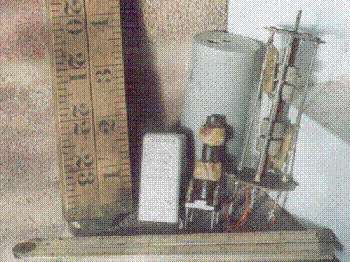
This is the best reason for large top capacitances on Tesla coils. It has little to do with coupling or matching, and nothing whatever to do with the theory propagated for years (around eighty years) that the spark length produced by the secondary has something to do with the Q of the secondary. That theory is wrongly applied to spark transmitter-driven Tesla coils, it applies to double tuned intermediate frequency transformers (IFTs) which, though related closely to Tesla coils, are in subtlety very different, largely because of the fact that IFTs are fed by continuous waves, and it predicts the largest sparks for the smallest secondary capacitances. A couple of IFTs are shown below. The coils and capacitors can be clearly seen.
The theory given above is in agreement with experiment, that it is the total charge on the top electrode which determines the spark length and this increases with secondary capacitance for spark transmitter-driven coils. The only useful function performed by Q in spark transmitter-driven Tesla coils is to provide for an efficient transfer of energy from primary to secondary under conditions where an iron core cannot be used for obvious reasons. Here it is sufficient for the unloaded Q of the secondary to be say at least ten, since all it needs to do is couple the wattless power accumulated by the primary capacitor. Hence my old 500VA coil secondary, battle scarred by direct strikes and with a measured unloaded Q of just 35 gave just as good results as when it was new.
However, valve-driven coils need a high secondary Q. This is because the secondary system of a valve-driven coil has to perform the wattless power accumulation which in a spark transmitter-driven coil is performed by the energy storage on the primary capacitor prior to spark discharge across the primary gap. In the case of valve-driven coils, a small top load will prove beneficial because the Q - important in a valve-driven circuit - decreases with increasing capacitance, just as with an IFT. Here, spherical top loads are likely to be better than toroids, since a high breakdown voltage will allow a large charge prior to dielectric breakdown of the air, and the small capacitance will keep the Q high. Evidently there is a compromise to be made between the maximum charge for a given energy and the large Q which is needed to allow the necessary charging current to be built up over a large number of cycles.
This is one of the reasons why the theory developed for IFTs cannot be applied in the same way to spark transmitter-driven Tesla coils - the IFT is a "continuous wave" system whilst the spark transmitter-driven Tesla coil is in essence a "one-shot" system. The other reason why the theory which was developed for intermediate frequency transformers cannot be applied to Tesla coils generally, in exactly the same way as it is to IFTs, is simply due to the difference in the form of the secondary capacitors. In the IFT the secondary capacitor is of the conventional multi-plate type, and any net charge on the "live" plates induces a corresponding opposite charge on the "earthed" plates, which are physically very close to them. The electrostatic fields from these charges are equal and opposite throughout all space, except in the very close vicinity of the plates, and it is only between the plates and in the dielectric where a significant field exists. (This is analogous to the cancellation of fields found in parallel conductor transmission line systems.) Even this is minimised by the presence of the dielectric, since a dielectric works by reducing electric fields by polarisation. There is thus no net field external to the capacitor of any consequence, and the only voltage which is measured is the potential difference between the plates, which increases as the capacitance is reduced.
In the Tesla coil, the secondary capacitor is an isolated electrode, effectively in "free space". The electrostatic field developed by any charge on this electrode does indeed induce opposing charges on surrounding objects in the vicinity, but these are removed by some considerable distance and the local field is not counteracted by them.
The local field generated by the charge q is given by:
![]()
where q is the charge in coulombs, r is the radius in metres, 4pe0 = 1,11265 x 10⁻¹⁰ and E is the electrostatic field in volts per metre. Thus we have the apparent paradox that the biggest sparks are produced in the spark transmitter-driven Tesla coil when the potential across the Tesla secondary is low and the top capacitance large. It is the charge q in the bottle which "does the damage", exactly as for the Van de Graaf generator. The spark length is dependent on the charge. If we have two Tesla coils, one of which has double the charge on its topload than the other, the greater charge will produce a spark 1,4 times (square root of the charge ratio) as long, to a good approximation.
The potential in volts at any distance from this charge is:
![]()
I am still puzzled over the exact mechanism which determines spark length for a given q, undoubtedly it revolves around an equilibrium of forces, but am reasonably assured that this will follow given that (after eighty years of misunderstanding) the mechanism of operation of the Tesla coil is now plain. I am enormously relieved that it can be explained in terms of known theory.