Alternator,
Arc and Spark. The first Wireless Transmitters.
"Anyone who has had
actual contact with the making of the inventions that built the radio
art knows that these inventions have been the product of experiment
and work based on physical reasoning, rather than on the
mathematicians' calculations and formulae. Precisely the opposite
impression is obtained from many of our present day text books and
publications."
Edwin H. Armstrong
The
origins of wireless, as it was then known, are to this day the
subject of occasional dispute. Suffice to say that many independent
scientists and engineers contributed something of significance as
will be shown below, but it was the youthful Marconi who in the 1890s
drew the threads together and, via his family's substantial business
contacts and not inconsiderable wealth, plus his own indisputable
talent for scientific investigation and improvisation, made a
commercial success of it. It is also worthy of note that the company
Marconi established one hundred years ago and which bears his name is
still doing business today.
However,
it is beyond doubt that had Marconi not commercialised wireless when
he did, then somebody else would have done so very quickly. The
evidence for that is in the great rapidity with which Marconi found
himself to have competitors in the new technology, many of them
commercially successful, some of them embarrassingly so. For example,
Germany's first antenna installation was erected by Professor Slaby
and Count Arco on the tower of the "Heiland" Church in
Sacrow in August 1897, their first successful transmitting
experiments having covered half a kilometre in June of that year,
only three months after Slaby had witnessed a series of
demonstrations by Marconi on Salisbury Plain. This should be compared
with Marconi's demonstrations on Salisbury Plain only one year
previously, in September 1896, which covered 2.8km. The efforts of
Slaby and Arco were later joined with those of Professor Ferdinand
Braun and the firm of Siemens Brothers and Halske, from which union
the giants AEG and Telefunken were born - two more commercial names
still very much with us today.
The
essential elements of wireless were thus well known to many people
and the technology for developing alternating current at radio
frequencies (r.f.) widespread and generally well understood. Many a
nation could boast its own expert, from the great Indian scientist
Sir Jagadis Chandra Bose FRS who in the 1890s developed practical
microwave and semiconductor technology, to the Canadian Fessenden,
the Dane Poulsen, the Englishman Professor David Hughes who in 1879
failed to impress his learned friends in the Royal Society with his
discovery and a multitude of others, including of course the Balkan
genius of Tesla and the American dentist Mahlon Loomis whom many
acknowledge to have carried out the first successful experiments many
years before anyone else in the 1860s but without obtaining any
publicity or financial backing.
There
were three methods of producing r.f. power prior to the work of
Fleming and De Forest, which latter of course issued in true
continuous wave generation of high purity, at high efficiency and
modest expense through the thermionic valve. These "pre-electronic"
methods were:
High frequency
alternators. The main exponents of this, Ernst Alexanderson
and Professor Goldschmidt, produced high speed rotating machinery to
generate the desired power directly, exactly as Tesla had done for
George Westinghouse's household low frequency a.c. distribution
system in the USA years before. Indeed, the first successful r.f.
alternator was made by Tesla himself in 1899 and operated at 30kc/s.
Alexanderson was Swedish by birth but spent most of his life in
America and produced his alternator for the Canadian Reginald
Fessenden, who was once chief chemist and engineer for Thomas Edison.
Fessenden himself was the inventor of many significant devices, one
of which, the "roller coaster" variable inductor, is still
in use today. It was with one of Alexanderson's alternators, suitably
tweaked by Fessenden, that the first voice broadcast took place on
Christmas Eve 1906. The technique was expensive to apply because of
the high rotational speeds and high electrical losses at high
frequencies, but nevertheless enjoyed considerable commercial success
and gave rise to the first true continuous wave (sine wave) wireless
transmissions of high spectral purity, though it had the great
mechanical limitation of being restricted to comparitively low
frequencies, up to 100kc/s. This could not compare with spark, which
was used at over 1.5Mc/s, but the trend at the time was to longer and
longer wavelengths and lower frequencies, where the alternator could
compete exceptionally well. Indeed, one notable Marconi spark station
in the USA was replaced by an alternator of Alexanderson's design.
Efficiency was not impressive in the smaller versions, over 10
horsepower (7.5kW) input being required for 2kW output, there being
great heating losses in the copper windings and iron armature and
frictional losses in the gear trains used to achieve high rotational
speeds of 20000rpm.
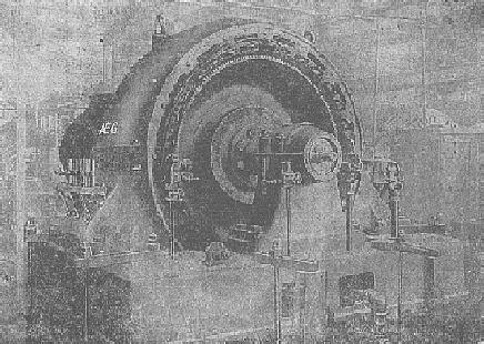
In
Germany a somewhat different strategy was developed based on
frequency multiplication. This was sometimes referred to as "the
Arco system" and such an alternator, built by AEG, is shown in
the photo (apologies for the quality - the original is of very poor
contrast). Telefunken made some large machines, one water cooled of
400kW was installed at Nauen and opened for business with great
festivities in 1920; it escaped the penalties associated with high
rotational speeds, and high frequency copper and iron losses by using
the frequency multiplication technique, which was based on saturable
transformers having a dc winding, to produce a range of possible
output frequencies based on the relatively low 6kc/s output from the
generator. The rotor measured 1.65m in diameter and weighed seven
tons, the output was 450 amps at 1200V. The output could be on-off
keyed by spoiling the frequency multiplying action of the first of
the chain of multiplying transformers by a resistance keyed in and
out of one of its windings, which was a great advantage over the
rival arc transmitters. The antenna current was typically 400 amps
with a feedpoint voltage of 80kV or more and the transmitter was
keyed mechanically at 80 words per minute (wpm); others of this
period in the USA at New Brunswick and Annapolis could be keyed at
100wpm, and all without sparking at the contacts!
A
lot of development work was done on the frequency-multiplying
transformers, since these extended the utility of the alternators,
which could only generate the higher frequencies by using very high
rotation rates and losing much power in iron and copper losses.
These transformers were generally 90% efficient, but because of the high powers normally used were cooled in an oil bath, which also aided insulation
at high frequencies, oil insulation being even more effective at high
frequency than at low as Tesla had shown years before. Latour
developed a frequency-multiplying transformer which could be used for
producing the third or fifth harmonic at will, and without needing a
dc winding on the core. He used a special nickel steel alloy, which
saturated at low magnetic field and which had low hysteresis -
probably a forerunner of the more modern permalloys and the like. A
transformer of his, for 12-15kW, used just 500 grams of nickel steel
and lost only one kilowatt in heat. It was used for tripling 33kc/s
to 100kc/s.
The
Nauen station building still exists and is still used for radio
transmission, which must make it one of the oldest monuments to
wireless which has been in continuous use for the purpose for which
it was built, though the alternators it once housed have long gone.
One large working example of these magnificent machines, built
according to the Alexanderson method, remains at Grimeton in Sweden,
and is run up ceremonially each year. Alexanderson has left us with
another legacy in the form of the magnetic amplifier, a saturable
reactor which is controlled by a dc winding. It was with this that
Fessenden modulated the alternator output for his 1906 broadcast and
magnetic amplifiers of many forms are still used for a wide variety
of purposes today.
The
electric arc. In 1898 a Dr. Simon from Frankfurt had noticed
that the electric arc could be made to sing by means of a modulating
voltage on the arc supply. After a number of experiments he showed
that the electric arc made a reasonable loudspeaker which he
demonstrated in public auditoria. Also, the modulated arc produced
not only sound but a modulated light beam by means of which the
German Navy managed to make intership telephone calls using a
modulated arc searchlight and a photosensitive selenium cell. In
England, William Duddell, an electrical engineer responsible for
inventing the moving coil oscillograph (an early device for the
photographic recording and observation of oscillating audio frequency
waveforms which was still in use in the 1940s) and the
thermo-galvanometer (later used for measuring antenna currents and
still used in slightly modified form today) discovered that by
placing a series tuned circuit across the arc, audio frequencies
could be produced by spontaneous oscillation without the need for a
separate modulating supply, but that the efficiency plummeted as the
frequency was increased. In 1899 Duddell demonstrated a musical
instrument which was based on this discovery. The Danish inventor,
Valdemar Poulsen, who had demonstrated the 'Telegraphone' (the
world's first magnetic recording device) at the Paris exhibition of
1900, turned his inventive genius to the problem and by means of a
water cooled copper anode and by making the discharge occur in an
atmosphere of hydrogen or illuminating gas, succeeded in raising the
efficiency and frequency to the desired level; Poulsen's arc could
generate frequencies of up to 200kc/s or so and he patented it in
1903.
The
Poulsen system and its variants were enormously successful, much to
Marconi's chagrin; the American Navy in particular seemed very keen
on them. The use of a reducing atmosphere meant that glowing
particles of metal oxides could not be formed, and it was these
particles of incandescent metallic oxides, which at high temperature
emitted thermionic electrons into the arc - a phenomenon explained in
1904 by Wehnelt and later exploited in the "dull emitter"
cathodes of indirectly heated valves - which had extended the
quenching time of the arc in air and limited the experiments of
Duddell. Even hot metal particles could prove troublesome and to
eliminate as far as possible the effect of electron-emitting
particles, the arc of larger transmitters was placed in a strong
magnetic field in order to sweep these out of the system and improve
the quenching. Arc transmitters were widely used and scored some
notable successes, the Belgian experimenter Robert Goldschmidt using
one for voice broadcasts at Laeken and only closing down his station
shortly before the invading troops of Kaiser Wilhelm arrived at the
onset of war.
 The
technology to build large arcs had already been created for the
chemical industry in 1902 (the "Atmospheric Production Co."
based at Niagara Falls) and subsequently brought to a high state of
efficiency by two Norwegians, the physicist Prof. Kristian Birkeland
and the engineer Dr. Samuel Eyde, in order to fix nitrogen as
nitrogen oxides, which could then be dissolved in water to make
nitric acid, nitrate fertilisers and explosives. Calculation
indicates that around 8kWh was needed to produce one kilo of
concentrated nitric acid, and thus these massive arcs could only be
sited where there was an abundance of "white coal" - water
power. It is no coincidence that Dr. Samuel Eyde went on to become
the first president of the famous Norsk Hydro company, remembered by
most in connection with the 'Heroes of Telemark' who sabotaged heavy
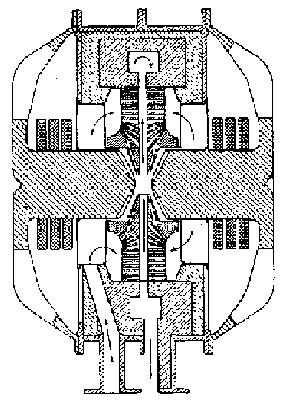
water production in the Second World War. A diagram of a Birkeland
and Eyde arc is shown to the left.
The
technology to build large arcs had already been created for the
chemical industry in 1902 (the "Atmospheric Production Co."
based at Niagara Falls) and subsequently brought to a high state of
efficiency by two Norwegians, the physicist Prof. Kristian Birkeland
and the engineer Dr. Samuel Eyde, in order to fix nitrogen as
nitrogen oxides, which could then be dissolved in water to make
nitric acid, nitrate fertilisers and explosives. Calculation
indicates that around 8kWh was needed to produce one kilo of
concentrated nitric acid, and thus these massive arcs could only be
sited where there was an abundance of "white coal" - water
power. It is no coincidence that Dr. Samuel Eyde went on to become
the first president of the famous Norsk Hydro company, remembered by
most in connection with the 'Heroes of Telemark' who sabotaged heavy
water production in the Second World War. A diagram of a Birkeland
and Eyde arc is shown to the left.
The
magnet poles (diagonally shaded) are horizontal to the left and right
of the central arc chamber, and on each pole can be seen three
separate magnet windings. The copper arc electrodes, which are hollow
and drilled with many holes through which air (shown by the arrows)
circulates, are above and below the magnet poles.
Many
arc transmitters were commissioned, few of which needed the
prodigious power plants associated with the Birkeland and Eyde
process. Most were of a few tens of kilowatts or less, but there were
stations of 100kW or above at Lyons, Nantes, Paris (Eiffel Tower),
Rome, Saloniki (the Thessalonica of the New Testament), San
Francisco, Hawaii and at least eight more in the USA, Cairo, Horsea
Island and Portsmouth, these last two in England where their presence
must have made Marconi wince.
A
few truly gigantic arc stations were built, of Birkeland and Eyde
proportions, and were the most powerful of all early radio
transmitters. Having scanned an admittedly ancient copy of the World
Radio and Television Handbook I cannot actually find anything from
our own time which compares with the biggest of the old arc stations.
The Dutch East Indies, as they then were, boasted a monster of 3.6
megawatts (input power). The copper windings for the electromagnet
which helped quench the arc weighed twenty tons. This transmitter was
situated at Malabar, was designed by a very appropriately named Dr.
de Groot ("Groot" in Dutch means "big") was still
active in the early 1920s and transmitted on 6100m (49.2kc/s) using
the callsign PMM. The power generation, at 25kV, was by an American
General Electric hydroelectric plant at Pengalengan. As if de Groot's
giant was not enough, there were three more Poulsen arcs at Malabar,
plus a "whistling spark" transmitter as well - the Dutch
authorities were evidently taking no chances. Another giant was the
French station at Bordeaux, known as Lafayette or Croix d'Hins, which
had eight masts 250m (820ft) high, covered an area 1.2km by 400m, had
an earthing system of one hundred square metres of copper plate
connected by one hundred copper tubes, buried 20m deep in the ground
(which is probably still there!) and ran one megawatt. The
transmitter itself weighed eighty tons, the majority of that in the
electromagnet. It transmitted on any one of seven wavelengths between
13850 - 23500m (12.8 - 21.7kc/s) but was doomed, as were all arc
transmitters, by the fact that the arc had to burn continuously and
thus morse transmissions were by frequency shift keying (fsk) in
which the transmitter was switched between two slightly different
radio frequencies separated by a few kc/s. Whilst some of the smaller
arc transmitters were used for voice transmissions or, for morse
purposes, could key on-off by dumping the output into a resistive
load, megawatt-sized dummy loads were then as now in short supply and
the frequency-shifted output from an fsk-operated arc was inevitably
dumped into the 'æther'. (Perhaps they should have used a Tesla
coil as a dummy load . . .)
The odd megawatt of power
shifting its none-too-clean frequency footprint up and down the
waveband by a few kc/s generated more than a fair amount of
interference as may be expected. Surprisingly, this only became
objectionable when receiver technology improved (the price of
progress!) as the receivers originally used to detect spark
transmissions were very sensitive to the jagged damped wave trains
generated by spark, but were relatively deaf to the more nearly
undamped sinusoidal emissions of the quenched arc. If you wanted to
receive arc transmissions, you had to use a special receiver, such as
Professor Pedersen's "tikker" or Fessenden's heterodyne
receiver, and thus other spectrum users with sets sensitive only to
spark transmissions weren't offended by the harmonic-rich output of
an fsk-operated arc - but that changed when after the First World War
everyone went over to the new electronic technology, the thermionic
triode, which could not distinguish between alternator, arc and spark
and was sensitive to the lot.
In England, radio amateurs
had their apparatus confiscated during the First World War,
purportedly to prevent espionage, but also because the Post Office
wanted to clamp down on 'interfering radio amateurs'. This did not
unduly impress the radio hams, who by and large caused little trouble
(though one indignantly refused to surrender his equipment and was
sentenced to six months in jail by the unsympathetic authorities) and
when the Post Office opened a large arc transmitter at Leafield near
Oxford in 1920 operating on 12200m the interference caused by this
official source received a somewhat critical response. To add insult
to injury, the British Post Office now insisted that amateur
transmitting licences should carry a hefty price tag as a deterrent,
and after a somewhat heated exchange of words, radio hams got their
apparatus and transmitting licences back at a more reasonable price.
Given the low frequency fundamental, the harmonics from an arc
transmitter would be spaced, in the case of the Leafield station,
every 25kc/s or so on up the spectrum for hundreds of kc/s like teeth
on a comb, each 'tooth' jumping a handful of kc/s from side to side
as the transmitter was keyed. This pretty well knocks the present day
radio ham's complaint of television timebase interference into a
cocked hat, and a Paris conference in 1920 had decided that all such
transmissions should be prohibited, though Leafield and Dr. de
Groot's mercifully distant masterpiece seem to have lingered on for a
while.
Happily, fsk is still
with us and is used, in far more spectrum-friendly guise, in a
variety of narrow-band data modes. The great arc transmitters have
all gone, and little other than their means of modulation remains of
their contribution to the art of wireless. A one megawatt arc,
intended for the U.S. Navy, but cancelled at the end of the First
World War, made its way by a circuitous route to the University of
California at Berkeley where its large magnet formed the basis of Dr.
Lawrence's cyclotron in the 1930s. This cyclotron has been preserved
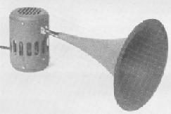
at the Lawrence Radiation Laboratory as a memorial. Curiously, Dr.
Simon's singing arc which started the ball rolling, made a brief and
unspectacular reappearance in the 1950s. A Parisian inventor, Sigmund
Klein, patented a new type of loudspeaker called the "Ionophone".
It consisted of a radio frequency corona discharge inside a quartz
tube which opened into an exponential horn. The radio frequency
discharge was amplitude modulated by the incoming audio signal and
this, coupled to the horn, produced extremely high quality sound
reproduction at high frequencies. It was briefly manufactured in
England and also in France, but was not a commercial success. The
Ionophone is shown below.
Spark,
a.k.a. Damped Waves, alias 'Mode B'. The great spark
stations, like the arc stations, have long closed down, but as in the
case of arc and alternator stations have in a number of cases left
behind buildings and antenna bases and guying blocks (see Peter
Jensen's excellent 1994 book "In Marconi's Footsteps - Early
Radio" ISBN 0 86417 607 4) although perhaps surprisingly they
too have left vestiges of their technology behind them in strange
places. The current high-tech amorphous alloys are made by a process
which owes more than a passing debt of thanks to the first toothless
rotary spark discharger used by Marconi at Poldhu in Cornwall in
1901, the high speed rotary cooling disk onto which the molten alloy
is poured giving a cooling rate of more than a million degrees per
second, so fast that the alloy doesn't have enough time to
crystallise, and quite good enough for quenching a 300kW spark.
The first commercial
development of the Poldhu rotary discharger was a variant having
teeth - the modification was so successful that the toothed from of
rotary gap is now thought of as the norm, but the original had no
protrusions from the disk. Unfortunately, the receivers of the day
worked at long wavelengths and had to retrieve spark signals from
amongst the crashing noises of natural static, the difference between
them not being very great and the toothed discharger gave a
characteristic rasping tone to the transmissions which aided the
operator in picking out the signals from the emissions of mother
nature. The toothless disk produced a more constant aerial current,
but the sounds this created in the headphones were less easily
distinguished from natural "interference". Marconi's first
sales of the new discharger were to the British Royal Navy and in the
photo the ten inch rotary disk, in the lower left, can dimly be seen,
labelled D; at least three of the protruding studs are visible. The
sound deadening cover is hinged open to allow the view.
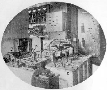
In the right foreground,
labelled K, are four of the eight condensers. The zinc plate and
glass condensers were immersed in oil and each was kept in a metal
tank - hence the origin of the name "tank circuit" to
describe the power output tuned circuit of a transmitter. This
illustration is of the Marconi 5kW "Battleship" set and was
installed on large warships of the Royal Navy in the First World War.
Amazingly, this photo was published during that conflict. Just how
likely would it be today for a major power to allow the publication
of a photo of one of its naval communications centres during wartime?
Chronologically, the
oscillating current produced by the spark discharge of a condenser
through a coil was of course the first method used to generate
electromagnetic radiation and it remained until long after arc and
most of the alternators had gone. From the experiments of Hertz and
Bose in the late 1800s, through the syntony of Lodge, the impedance
matching of Slaby, and the beginnings of (tuned and deliberate!)
spread spectrum technology during the First World War (the
"commutator receiver") spark generation of r.f. power
proved amazingly durable, surviving until well after the Second World
War. According to the British General Post Office "Handbook for
Wireless Operators" published by Her Majesty's Stationery Office
in 1954, spark transmission was still permitted on 500kc/s as
emergency signalling reserve for ships, lifeboats etc as fixed "by
Article 33 of the Radio Regulations", this referring to the
annexe to the International Telecommunication Convention of Atlantic
City, 1947. In 1954 it was still a requirement of both the Post
Master General's First and Second Class certificates that the holder
(subparagraph d):
"have a theoretical
and practical knowledge of the operation, adjustment, and maintenance
of Spark, C.W., I.C.W., R.T. and D.F. Installations, . . ."
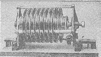
The spark transmitters
referred to were the peak of spark development and used the
multi-plate discharger of Max Wien (though arguably invented by
Nikola Tesla) which formed the basis of most of Telefunken's spark
sets and was the source of the "whistling spark" used by
many stations and commonly known as the "quenched" spark
gap, and a Telefunken gap of this type is shown above. Spark
transmitter theory still featured in the written examinations of the
period, as evidenced by the appearance of the terms decrement and
damping in this 1954 specimen question for the Second Class
certificate, for which the theoretical knowledge was only expected to
be "elementary":
"Define the terms
'wavelength', 'amplitude', 'decrement', and 'damping'. Find the
resonant frequency of a circuit consisting of a coil of 500
microhenries inductance in series with a capacitor of 2,000
picofarads."
This examination question
from barely fifty years ago seems a pretty good starting point for a
discussion on how to optimise the output of a spark transmitter for
the purpose of coupling it to a Tesla coil.
Back
Homepage