Conductors at Radio Frequency
"Mathematics . . .
a kind of lazy-tongs by means of which conclusions may be reached
without straining the intellect."
Alfred M. Still
I have a problem. What is
the better form of conductor to use at radio frequency? Is it a tube
or is it a flat strip? The problem is not made any easier by the fact
that one contender expresses his views non-mathematically in a way
which is at once easy to grasp, appeals to the reason and exercises
one's appreciation of some fundamental physical realities, whilst his
opponents state theirs in terms of partial derivatives and Bessel
functions. But let me introduce the contenders.
In the red corner, the
late, the great, Frederick Emmons Terman, ScD, Professor of
Electrical Engineering and Dean of the School of Engineering,
Stanford University; Past President of the Institute of Radio
Engineers, author of "Radio Engineering", "Radio
Engineers' Handbook" etc etc.
In the blue corner, the
almost-unheard-of Mr. A.G. Warren, late of the Armament Research
Department, Ministry of Supply, ably aided and abetted by the late
Professor Alexander Russell, Fellow of the Royal Society, the late
Professors C.L. Fortescue and G.W.O. Howe, the internationally
renowned Mr. S. Butterworth designer of filters extraordinaire and
that Victorian bastion of the scientific community, His Lordship the
late Lord Rayleigh, whose collective achievements and honours would
fill (and do fill) several books. It should be noted that Messrs.
Russell, Fortescue, Howe, Butterworth and Rayleigh each contributed a
significant portion to our knowledge of the flow of alternating
current in metallic conductors at high frequencies. Also sticking
their oar in for the blue corner (a rowing blue no doubt; somewhat
unsportingly in my view) we have apparently the assistance of the
Bureau of Standards, Washington.
Right now it doesn't look
too good for Professor Terman, but it has been known for more
hopeless cases to rise triumphant.
Let me state the cause of
the dispute.
Professor Terman says (p.
20, "Radio Engineering") that a flat strip conductor is not
a good choice for radio frequencies since the interaction of the
current with the magnetic flux it produces will, by virtue of
producing the skin effect, force the current to flow down the two
opposite edges of the strip and hence the majority of the surface is
unused as a conductor. The suitability of a conductor for radio
frequencies is not a simple matter of its surface area, but the
disposition of the conductor in space is a vital factor. He implies
that a tubular conductor of circumference equal to the width of the
flat strip is always to be preferred.
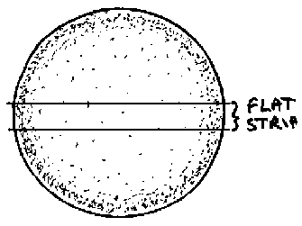 Dr.
Cadd (that's me) adds by way of comment that it is easy to see
Professor Terman's point by considering a cross-sectional view
through a circular wire carrying radio frequency current. By the skin
effect, the radial current distribution decreases exponentially from
the outside, tending thus to be concentrated in an annulus around the
circumference of the wire. A flat strip is simply a thin slice taken
across the diameter of the wire, in which the current flows down the
two edges, exactly as Professor Terman states.
Dr.
Cadd (that's me) adds by way of comment that it is easy to see
Professor Terman's point by considering a cross-sectional view
through a circular wire carrying radio frequency current. By the skin
effect, the radial current distribution decreases exponentially from
the outside, tending thus to be concentrated in an annulus around the
circumference of the wire. A flat strip is simply a thin slice taken
across the diameter of the wire, in which the current flows down the
two edges, exactly as Professor Terman states.
So far, so good. Now it's
Mr. Warren's turn. Mr. Warren says . . . actually, Mr. Warren doesn't
say much at all, leastways not in English, and therein lies
half my problem. Mr. Warren mutters various obscure incantations,
inscribes mystical symbols and makes peculiar signs with his learned
pen which only the truly wise and enlightened may comprehend the
significance of. However, I do not hold that against him, nor do I
see any great reason to curtail his views simply because they are
expressed in a language other than my own. Unfortunately, he does go
on a bit; succinctness is not a strong point of his. Mr. Warren, the
webpage (and half of cyberspace) is yours .....

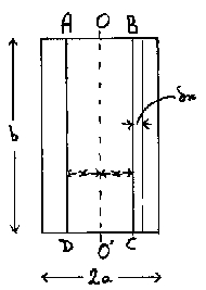 The
wide parallel strip is represented as in the diagram where it is
shown in cross-section. Its width is b , its thickness 2a ;
b >>2a. The current flows in a direction
represented by the normal to the paper (or screen - Ed.). At a
distance x from the mid plane OO' the current density is g
, the intensity of the magnetic field is H (directed along BC, or
CB), the flux per unit length within the conductor, and to the right
of BC, is f; the external flux to
the right of the conductor is f';
the current within the section OBCO' is Ix ; the
potential difference per unit length of the conductor is e .
Proceeding round the path ABCD the current enclosed is 2Ix
and therefore the magnetomotive force is 8pIx
. This is equal to H x 2b .
(In what follows, m is the magnetic
permeability of the conductor, w is
2pf, r
is the resistivity of the conductor and j is the square root of -1.
Ed.) Hence
The
wide parallel strip is represented as in the diagram where it is
shown in cross-section. Its width is b , its thickness 2a ;
b >>2a. The current flows in a direction
represented by the normal to the paper (or screen - Ed.). At a
distance x from the mid plane OO' the current density is g
, the intensity of the magnetic field is H (directed along BC, or
CB), the flux per unit length within the conductor, and to the right
of BC, is f; the external flux to
the right of the conductor is f';
the current within the section OBCO' is Ix ; the
potential difference per unit length of the conductor is e .
Proceeding round the path ABCD the current enclosed is 2Ix
and therefore the magnetomotive force is 8pIx
. This is equal to H x 2b .
(In what follows, m is the magnetic
permeability of the conductor, w is
2pf, r
is the resistivity of the conductor and j is the square root of -1.
Ed.) Hence
or
From equation 1
From equations 4 and 5
Differentiating this with
respect to x gives
Assuming that g
varies sinusoidally and interpreting equation 6 as a vector equation
one obtains
the solution to which is
Since g is the
same for ±x , A1 = A2 and the
solution may be written
or
The current per centimetre
width of the conductor is
or
If

then at the surface

and therefore the
impedance per centimetre of 1cm width of the conductor is
(This impedance does not
include the "external" reactance; this does not matter
since Z1 is being determined to find R1, the
resistance of 1cm width of the strip.)
Writing
and

Writing

we obtain
giving
Putting 2a = t
, the thickness of the strip, gives
where R1 is the
resistance of a strip 1cm wide.
At low frequencies (mains
power frequencies) equation 15 may be used to determine the increase
in resistance due to eddy currents. To the first order, when a
is small,
For copper, k =
0.215f½ and
therefore a = 0.152f½.
At f = 50, a = 1.075. For a strip
1cm thick at = 1.075; sinh 1.075 =
1.2943; sin 1.075 = 0.8796; cosh 1.075 = 1.6356; cos 1.075 = 0.4757;
and so
an increase of resistance
of 0.74%.
An approximate expression
for l when at
is small, is
At high frequencies, when
at becomes big, sinh at
and cosh at become equally very
great, while sin at and cos at
remain finite so that the resistance of unit width of strip
approximates asymptotically to ra/2.
Thus at f = 106, a = 152 and
a strip of considerable thickness would have a resistance of
76r, independently of the
actual value of the thickness. It is clear, however, from equation
15, that at a constant frequency, as the thickness is increased, the
resistance passes through a number of maxima and minima. A strip of
finite thickness may have a lower resistance than one which is
indefinitely thick. Using the same nomenclature as for equation 14,
then if

Maximum and minimum values
occur when
or

Since both S and s being
zero corresponds to a conductor of no thickness this case cannot be
considered. S <> 0, therefore s = 0 for a maximum or minimum
value.
At maximum or minimum
values at =
p, 2p, 3p,
4p, etc. When at
= 2np, cos at
= +1 and
When at
= (2n + 1)p, cos at
= -1
Successive maximum values
of R1 are
Successive minimum values
of R1 are
The particular value of
interest is tanh(p/2) = 0.917; all
subsequent values differ from unity by only a negligible amount. For
this case, when at = p,
i.e. t = p/152 = 0.0206 cm, the
resistance is 8.3% less than the resistance of a thick strip.
Thank you Mr. Warren. It
appears then from your work that a copper strip just a shade over
0.2mm in thickness has a resistance at 1Mc/s (a
= 0.152 x the square root of frequency) which is over 8% lower than
any other thickness. Unfortunately, Mr. Warren does not see fit to
extending the argument to tubular conductors, which presumably follow
a similar pattern.
 The
difficulty I have with this is that effectively this is saying that
flat strip conductors are good at radio frequency, which disagrees
with Prof. Terman. The specific argument I will pick with Mr.
Warren's argument is that he has chosen from the beginning the way in
which the current distributes itself over the conductor
cross-section. Is there any good reason for not doing the
calculations with the geometry as shown here, and then working out
how the balance of factors distributes the current over the strip?
The
difficulty I have with this is that effectively this is saying that
flat strip conductors are good at radio frequency, which disagrees
with Prof. Terman. The specific argument I will pick with Mr.
Warren's argument is that he has chosen from the beginning the way in
which the current distributes itself over the conductor
cross-section. Is there any good reason for not doing the
calculations with the geometry as shown here, and then working out
how the balance of factors distributes the current over the strip?
I would also suggest
reaching the desired answer by considering a gradual perturbation of
the system, by drawing the circular wire shown beside Professor
Terman's argument through progressively more oval dies of equal
circumference and noting the redistribution of current at each stage,
until the last die is rectangular and of thin section.
Presumably, depending on
frequency, resistivity, dimensions and current, an equilibrium will
be reached between the penetration of the current and flux into the
strip, and the forces tending to move the electron flow to the
surfaces and to the edges of the strip. That is the computation
which needs to be done in order to decide the current distribution
and hence the strip resistance.
So is Professor Terman
right or wrong when he says that a flat strip is not a good choice at
radio frequencies? Evidently the basis for the calculations is here.
But how to actually do
it?! I have no idea, the mathematics are quite beyond me. Perhaps
someone has measured the radio frequency resistance of a strip and a
tube of the same thickness on a bridge and factored the resistances
according to the width of the strip and the circumference of the
tube. I just wish I could find the answer somewhere.
The next section concludes the journey from the generator to the load with a look at inductive coupling.
Back
Homepage