|
|
|
The text below is an edited version of JPS's postings giving an introduction to Track Editing.
Firstly, you'll need to be using 3D Studio MAX because Zmodeler and Modeller's Garage won't cut it in this case. Unfortunately 3D Studio is commercial software and is not available to download legally on the net so you'll need to find another, hopefully, inexpensive source. It really is a tragedy that the Speedsims Track Editing forum was lost because all of this was covered quite well back then. Why that forum wasn't restored from a backup baffles me. You won't find a many decent tutorials or info for lofting on the Internet. In fact, with every passing month there is less and less free info available about lofting. You'll find a lot of broken links now, even though the links to other tutorials still work. One guy even pulled his lofting pages off the web on purpose and moved them into a tutorial set that you now have to buy (jeezzzz! real community spirit there, eh?) I know these two pages are still available:
To start your track get a good map of the track that is to correct scale and set it as the viewport background (top view, obviously). Get your units set to 1 unit = 1 metre and the grid turned on, zoom the viewport out until the measure of the grid is correct against the real-world dimensions of the track. This is pretty much a lot of guesswork unless you know for a fact that, say, the front straight is exactly 1200m long. Start creating a standard line (spline) and set the vertex type to "smooth". It doesn't matter where on the track you start from, it doesn't make any difference if it's the start/finish line or not. Draw the line down the centre of the pavement. Click to create a vertex only when necessary, create the minimum number of vertices you can get away with. Since all the vertices will be of type "smooth" you'll notice the line will sometimes bulge out as if it wants to go in another direction--ignore this for now and just keep plotting along down the center of tarmac. Just to give you some idea, a typical horseshoe shaped hairpin will typically require only 2 vertices to make (one placed just before the start of the turn and one just after the exit of the turn). Again, at this point don't be concerned if the line is bulging out in places, just make sure your vertices are in the center of the tarmac. When you end the line click the last vertex on top of the first vertex to complete the circuit. I believe it then asks you if you want to close the spline (or words to that effect), answer yes. At this point you'll have a pretty roughed-in line following the center of the pavement. For corners that need to be touched-up you can change the vertex type from "smooth" to "bezier" or when you're in a really tough situation choose "bezier-corner". DO NOT USE "corner" type vertices. Move the vertices around and tug-and-pull on the bezier handles until your line follows the center of the pavement all the way around the track as perfectly as you can. In some cases you might have to go back and actually add some additional vertices in order to achieve the perfect curvature to follow the center of the tarmac; you do this by clicking the "refine" button then click where you want the new vertex to be created (make sure you created the right type of vertex for the situation at hand--either smooth, bezier or bezier-corner). Be careful to not go overboard and add too many vertices. Most turns can be achieved with only 2 vertices, and I have never run across a turn so complicated as to require more than 4 vertices. Use the minimum amount you can get away with--you'll see why in the lofting step. Now go back and raise/lower individual vertices on the line to add the elevation changes. Again, to achieve the correct and smooth elevation changes feel free to use "refine" to add an additional vertex if you have to. You don't want any knife-edge elevation changes. Pay close attention to your measurements here, it's easy to over do it and end up with huge heights or really steep hills. Don't worry about getting this line too perfect first-try, you will be able to go back and adjust this line as much as you need to later. NOTE: do NOT attach this line to any dummy or to the "hierarchy". It should remain a free-floating object in the "schematics view". Also, never delete this line (the "path), it can come in very handy even much later in the track development process. To keep it from being exported into your .WRL all you have to do is hide it. I've been asked if the grass and such are also lofted. Well, you can loft the polygons for the rumblestrips and berms pretty well and also at least have the loft generate the spare polys that you can then pull on and stretch to form the grass and gravel traps. There are a few tutorials out there on how to loft terrain, but it always turns out to be pretty high-poly stuff; I don't bother doing it that way myself. An alternative is to just "extrude" the polys for the rumblestrips/berms/grass from the edges of the lofted tarmac when it's finished. You can push/pull on these new polys to form whatever you need. The good thing about doing it this way is that it is incredibly easy and fast, the drawback is that you will have to manually map those polys (if you loft them they can be automatically mapped to follow the curves and hills--cool stuff when it works!). With your "path" line selected, over on the command panel in the "modify" tab you will see a "General" section. In there are settings for "Interpolation" and a check-box for "Adaptive". I turn on "Adaptive"; it seems to result in smoother lofts and better polygon arrangement in some situations. You can turn this setting on/off at will at any time later if you want to compare how your resulting loft is effected. Sometimes if you try to insert another vertex, 3D Studio Max won't allow you to move any other vertex without thinking you have that one selected. To fix this you need to select the line, go into sub-object-vertex mode, Edit menu - select none. In the modify panel it should now indicate "0 Vertices Selected" just above where the "Geometry" sub-section starts.
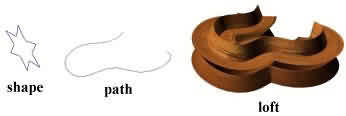
OK then, on to the next step, which unfortunately takes a lot of words to explain but is remarkably easy and quick. Everything I say here is based on 3D Studio MAX 3.0, the locations and perhaps even the names of some of these functions may be different in other versions of MAX and I really can't help you there. If you've gone through any lofting tutorials then you understand that lofting is the process of pulling one or more "shapes" along a "path" to form a 3D object. For example:
Hmmmm... that squiggly line looks kind of like a part of a race track. What if, instead of that stupid star "shape" we substituted a simple straight line? Pulling that along the squiggly "path" would probably yield something like a road, eh? So, somewhere out of harms way create a line (spline) that is perfectly straight and flat with only two vertices (the start point and the end point) and make them both "corner" type vertices. What I do is just splash down a rough line then go into vertex edit mode and use the transform type-in (F12) to move each of the vertices so they are exactly straight. Let's say vertex 1 is at (200,200,0) and vertex 2 goes at (212,200,0) which would be 12m to the right. The width of this line will be the width of the lofted pavement. I find widths between 8m-16m to be good for racing in SCGT. OK, now you've got your nice straight line. The next step is critical, but easy to forget: You want to make damn sure the "pivot point" of that line is exactly in the center because it will be pulled along the "path" based on where the pivot point is and how it is aligned. Select the "hierarchy" tab, click "Affect Pivot Only", then "Center to Object" and "Align to World", then click "Affect Pivot Only" again to exit that mode. Now then. You've got your "shape" and your "path" so you're ready to loft your track. Select your "path" line (the line that looks like your track). The "loft" function is rather hard to find in 3D Studio MAX 3.0: In the lower part of the command panel will now appear a whole set of loft settings and functions. "Well, ummmm.... Jeeezzz, JPS, it created something but it doesn't look too much like a road...what gives???" It will look a lot better as soon as we apply the right settings. At this point your loft should start looking more like a drivable road. If you were to apply a tarmac bitmap to it you could instantly make it look like tarmac. Let's go ahead and do that.... Create your material and link it to a road surface bitmap that you like. Apply your road surface material to the loft object. If you render the scene you'll notice that the material is probably heavily stretched along the length of the track (blechhhiieee!!). Let's fix it up nice and pretty.... In the loft settings go to the "Surface Parameters" section and start with these settings: The Length Repeat setting is critical to get right in order to make the tarmac look believable in-game. Length Repeat is exactly what it sounds like: how many times your road surface bitmap is repeated along the entire length of the loft. The correct setting depends entirely upon the length of your track and, frankly, comes down to a sort of guessing game to find the number that looks best for you. We've started with 40 and will increase/decrease that number until the road surface looks good. Set the viewport to "Smooth + Highlights" so you can see the materials in real-time; if your display system is incapable of this you will just have to resort to rendering it each time. Zoom in to a piece of the track close enough so you can see what the surface is going to look like. Change the Length Repeat to a larger number like 80 and see if the surface mapping looks better/worse. Keep increasing or decreasing this number in increments of 40 until it starts looking good then start adjusting it by 10 to fine-tune. I have had tracks that look great with a setting as low at 40 and others as large as 200, it all comes down to the length of your track and at what density your particular bitmap starts to look its best. If you want to get scientific about it, what you could do is use a 256x256 bitmap that had a perfect square shape drawn on it, and then keep adjusting Length Repeat until the repeating pattern formed perfect squares all the way down the road. At that point you would be certain that the bitmap is being repeated perfectly for the dimensions of the track, but, ehhh, who wants perfection anyway? Similarly, Width Repeat is how many times the bitmap is repeated across the width of the loft. Almost always you want this set to 1, but there are some rare situations where you would want it repeated multiple times; this setting allows you to achieve that. Notice also that you are allowed to specify fractional numbers like 1.5 or 3.25 to get just the effect you might need for those unusual situations. At this point you should definitely save your work. Let's switch back to wireframe viewing mode for this next part. Remember above in the "Skin Parameters" section I mentioned there would be more about the "Shape Steps" and "Path Steps"? Well, here you go: Shape Steps is essentially how many times across the width of your road polygons will be generated. A setting of 0 = 1 quad across, 1 = 2 quads across, 2 = 3 quads across, etc. Go ahead and play with that number and you will be see what I mean. You can see how playing with this number can instantly cause you to have a high-poly track that could be very FPS-
unfriendly for everyone. A setting of 0 works best in almost all cases. There are some cases where increasing the polycount across the width of the road is desirable in order to make the road smoother in areas where the pavement twists or banks to a significant degree and makes the road too bumpy in-game, but you would really only want to increase the number of polygons in those specific areas that need it, not the entire track--that would be a wasteful excess of polys. You could always loft those troublesome sections with a seperate loft using the same "path" and "shape" as your original track loft, and increase the Shape Steps for that second loft. Then just use the higher-poly track parts in the areas that need it and stick with the original loft for the rest of the track. Path Steps controls how many polygons are generated down the length of your road. Finding the best number for this setting comes down to "best feel" and "what looks best" and it is also greatly effected by how many vertices you have on your "path" line. You will notice that around curves and where hills start/end you need to increase the polycount in order to make it smooth. The other thing that greatly effects the poly density is the placement of the vertices on your "path" line. Remember plotting out all those "smooth", "bezier" and "bezier-corner" vertices? Notice how the loft increases the poly density based on those vertices. Notice also that how much you pushed/pulled on the bezier handles of those vertices also effects the ultimate density and arrangement of your track's polys. Let's see this in-action.... Un-select your loft and select your "path" line -- since it is underneath your loft it might be easiest to use the select-by-name feature (Edit - Select By - Name). Since the whole goal is to end up with a track that is smooth where it needs to be smooth, and low-poly along straights it is important to find the right balance between the "Path Steps" setting and the amount and placement of vertices. Yet you might not be able to make major changes to the vertices without changing the shape of your track too much. You also do not want to end up with sections where the polygons overlap each other. You can also experiment with changing some vertices from "smooth" to "bezier" or visa-versa, it shouldn't take too long to strike a good balance. If you have examined the construction of many of the original ISI tracks from SCGT and F1-2000 you will already have some idea of what to shoot for in your track surface.
Let's get this thing into the game and drive on it. What we'll do is cut the track into a couple of giant chunks and make up some really rough track files just for the sake of testing what it's like to actually drive on it. After driving on it you will have a better sense of what changes you should make to your loft to improve the track. Just a quick-and-dirty test here. DISCLAIMER: It is assumed you know and understand what the track files are, how they must be named, how to work on them, and how and where to save them so the game will use them. I won't cover here all aspects of what it takes to make a track from scratch and make it work in SCGT; such detailed information is best described in GT40-Steven's Track Editing Manual (TEM) which is available in the tutorials section of Mika Hirvonen's SCGT Site You should already have learned a lot by dissecting several of the original ISI tracks and modifying scene files to familiarise yourself with how it all goes together and how things are controlled by the scene files. Before we go further, make sure the .BMP you are using for your road surface is named so it matches up to a valid road entry in the TERRAIND.AIW file. Road surfaces typically start with the letters ROAD* or RD1*. If the name of your bitmap does not match a valid road terrain type in the TERRAIND.AIW file then rename it now so it does match, and update your MAX material so it points to the new bitmap name. Small but important divergence from the topic: A bit further off-topic: Right, back to getting the track into the game: Hide the original loft, path line and shape line so they are out of the way and you don't accidentally mess them up. Export the track just like you always export stuff. I always get the least problems when I export as triangles instead of quads, but some people say quads works fine for them. I have never heard anyone come up with a knowledegable explanation of why it works differently for different people. If you find you cannot drive on certain polygons on your track (as if they are phantom polygons or something) export it again as either quads or triangles until you find the setting that works in your case. Run your .WRL file through VRL2VRML. Be extremely patient! As your track grows in complexity it will start taking longer and longer to convert. It is not unusual for VRL2VRML to chug along for an hour, looking as if it has locked up, and then finally spit out the finished VRL's. It's not like a car that takes a mere 7 seconds to convert. When you've got your VRL's, it's time to start packing the MAS files for your track. You will also want a "skybox" (this is a background panorama and a clouds plane for the sky). What I do is just pull one out of an original ISI track and use it in my track; this is good enough for testing purposes. In the original ISI SCGT tracks the VRL's you need are usually named BKA.VRL and CLOUDSA.VRL. You will also need to get the BMP's that those VRL's use. Examine those two VRL's with a HEX editor and you'll see down at the bottom it lists the bitmap(s) that they use. Create the two MAS files for your track: one for the VRL's and one for the BMP's. Make sure you remember to include all the VRL's and BMP's for the skybox as well as your track VRL. Put those two MAS files into your MAS folder. Now it's time to create a simple Waypoint File (.AIW file) for your track: [SLOT00] The AVPos line is where you put those starting co-ordinates you wrote down a moment ago, but there's a little conversion you have to do to those numbers because the co-ordinate system inside SCGT is different than MAX. See the Track Editing Manual for details on the SCGT co-ordinate system. Next comes the Scene File (.SCN file): At the top of the file change the "DescFile=" entry to something that does not already exist on your machine. { InsStart=(0.0, 0.0, 0.0) InsOrient=(0.0, 0.0, 0.0) InsUseLTM=TRUE InsPlanes=(4) InsChange=False ObjFile=bka.vrl ObjStart=(0.0, 0.0, 0.0) LODIn=(0.0) LODMid=(3000.0) LODOut=(3000.0) ZOffset=(0.0) CollTarget=False HatTarget=False Zbuffer=False Child=clouds { InsStart=(0.0, 0.0, 0.0) InsOrient=(0.0, 0.0, 0.0) InsUseLTM=TRUE InsPlanes=(4) ObjFile=cloudsa.vrl ObjStart=(0.0, 0.0, 0.0) LODIn=(0.0) LODMid=(3000.0) LODOut=(3000.0) ZOffset=(0.0) CollTarget=False HatTarget=False Zbuffer=False } } *Note that CollTarget & HatTarget both must be set to False for these two objects. At the bottom of the file create a "group" and add in the instance definitions for your two track VRL's. It typically looks like this: Group=~fiaddba.scn Substitute the names of your VRL's for where I named mine "Trak001" and "Trak002". The name of the group is essentially irrelevant, it doesn't have to match the letters of your track. Make sure you have the "Response=Vehicle,Terrain" entries because that's what tells SCGT "OK, you are allowed to drive on the surface of this VRL." If it's not defined as terrain it's not going to allow you to drive on it. Also make sure you close off the "{}" braces sets correctly, otherwise wacky stuff can start to happen. Put your .AIW & .SCN files into your DAT folder, assuming you are a Ban-Scene enabled person, otherwise you're gonna have to go repacking them into your scene.mas file every time you make a change.
Let's see.... Sounds like it's time to drive: If your car does not start out on the pavement then fix your AVPos co-ordinates in the AIW file. If you car is facing the wrong way then play with the second value of the AVOrient line. What you want to look for first is whether the track is smooth enough to drive on at high speed, with no lethal bumps or sudden angles in the surface. Also check out the elevation changes, do they seem realistic? Are the turns relatively round and not choppy and angular? Is the pavement wide enough or too wide? Always keep that finalised loft (and the lines you used to generate it) tucked away somewhere because you may find yourself in a situation later down the road where you say to yourself "Damn! I wish I still had that finished version of the loft because it would come in handy for what I'm trying to do right now." If the track seems to be too wide, use the "Tape Measure" tool in 3D Studio Max to measure the width. If the "shape" line measures 12 then
the road width should also have turned out to be 12. I have not found a way to tell 3D Studio MAX that I want the path line to be considered to be un-scaled without it shrinking back to its original smaller size. Unfortunately, the easiest and safest thing to do is to make a new path line, considering the fact that you probably now have your viewport zoomed out to the proper size to trace the track map. |